6-2-2-p0723-0782-cxsj_en.pdf - 第16页
0 0.5 1 1.5 2 2.5 3 10 20 30 40 50 60 70 80 90 100 Maximum load mass W (kg) Cylinder stroke (mm) CXSJM CXSJL ø 6 ø 32 ø 25 ø 20 ø 15 ø 10 Weight Model CXSJM6 CXSJL6 CXSJM10 CXSJL10 CXSJM15 CXSJL15 CXSJM20 CXSJL20 CXSJM25…
When operating an actuator with a small diam-
eter and a short stroke at a high frequency, the
dew condensation (water droplet) may occur
inside the piping depending on the conditions.
Simply connecting the moisture control tube to
the actuator will prevent dew condensation
from occurring. For details, refer to the IDK s e-
ries in the Best Pneumatics No. 6.
Moisture
Control Tube
IDK Series
Dual Rod Cylinder/Compact Type
ø6, ø10, ø15, ø20, ø25, ø32
CXSJ Series
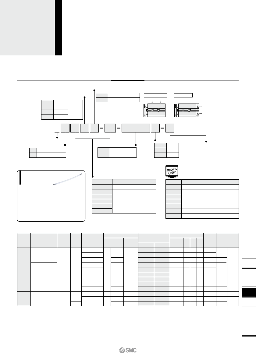
How to Order
50 M9BWCXSJ
Compact type
SM P6
Applicable Auto Switches/Refer to pages 1119 to 1245 for detailed auto switch specifications.
∗ Solid state auto switches marked with “
” are produced
upon receipt of order.
24 V
Special functionType
Electrical
entry
Indicator
light
Wiring
(output)
Load voltage
ACDC
Auto switch model
Lead wire length (m)
∗
0.5
(Nil)
3
(L)
5
(Z)
1
(M)
—
—
IC circuit
—
IC circuit
Applicable load
Perpendicular
In-line
IC circuit
—
IC circuit
—
IC circuit
—
Diagnostic indication
(2-color indicator)
Water resistant
(2-color indicator)
Yes
None
Yes
Grommet
Grommet
3-wire (NPN equiv.)
Pre-wired
connector
—
—
—
Relay,
PLC
—
Relay,
PLC
—
— 5 V
12 V
5 V
,
12 V
5 V
,
12 V
12 V
5 V
,
12 V
12 V
5 V
,
12 V
12 V
24 V
A96V
A93V
∗
2
A90V
A96
A93
A90
—
100 V
100 V or less
—
—
2-wire
3-wire (NPN)
3-wire (PNP)
2-wire
3-wire (NPN)
3-wire (PNP)
2-wire
3-wire (NPN)
3-wire (PNP)
2-wire
—
—
M9NV
M9PV
M9BV
M9NWV
M9PWV
M9BWV
M9NAV
∗
1
M9PAV
∗
1
M9BAV
∗
1
M9N
M9P
M9B
M9NW
M9PW
M9BW
M9NA
∗
1
M9PA
∗
1
M9BA
∗
1
Nil
TN
TF
Port thread type
M thread
Rc 1/8
NPT 1/8
G 1/8
ø6 to ø25
ø32
M
L
Bearing type
Slide bearing
Ball bushing bearing
Nil
P
Piping
Standard (ø6 to ø32)
Axial (ø6, ø10)
Port location
Standard piping
Axial piping
Port
location
Made to Order
(Refer to the below.)
Nil
S
n
Number of auto switches
2 pcs.
1 pc.
“n” pcs.
Bore size
6
10
15
20
25
32
Bore size/Stroke
Standard stroke
10, 20, 30, 40, 50
10, 20, 30, 40, 50, 75
10, 20, 30, 40, 50, 75, 100
(mm)
-XB6
-XB11
Note 1)
-XB13
-XC6
Note 2)
-XC19
-XC22
-XC85
Heat resistant cylinder (–10 to 150°C)
Long stroke type
Low speed cylinder (5 to 50 mm/s)
Made of stainless steel
Intermediate stroke (spacer)
Fluoro rubber seals
Grease for food processing equipment
Symbol
Specifications
Made to Order
Click here for details
Note 1) Except ø6, Axial type
Note 2) Slide bearing type (M) only
Solid state auto switch
Reed
auto switch
∗1 Water resistant type auto switches can be mounted on the above models, but in such case SMC cannot guarantee water resistance.
Consult with SMC regarding water resistant types with the above model numbers.
∗2 1 m type lead wire is only applicable to D-A93.
∗ Lead wire length symbols: 0.5 m ·················· Nil (Example) M9NW
1 m ·················· M M9NWM
3 m ·················· L M9NWL
5 m ·················· Z M9NWZ
• Since there are applicable auto switches other than listed, refer to page 747 for details.
• For details about switch with pre-wired connector, refer to pages 1192 and 1193.
∗ Auto switches are shipped together (not assembled).
Nil
Auto switch
Without auto switch
(with built-in magnet)
∗ Refer to the below table for auto
switch model numbers.
737
CX2
CXW
CXT
CXSJ
CXS
D-
-X
CXSJ
D
0
0.5
1
1.5
2
2.5
3
10 20 30 40 50 60 70 80 90 100
Maximum load mass W (kg)
Cylinder stroke (mm)
CXSJM
CXSJL
ø6
ø32
ø25
ø20
ø15
ø10
Weight
Model
CXSJM6
CXSJL6
CXSJM10
CXSJL10
CXSJM15
CXSJL15
CXSJM20
CXSJL20
CXSJM25
CXSJL25
CXSJM32
CXSJL32
Standard stroke (mm)
10
0.047
0.048
0.099
0.106
0.198
0.218
0.345
0.375
0.506
0.516
1.022
1.032
20
0.057
0.058
0.114
0.121
0.219
0.239
0.371
0.401
0.544
0.554
1.078
1.088
30
0.067
0.068
0.129
0.136
0.240
0.260
0.397
0.427
0.582
0.592
1.134
1.144
40
0.077
0.078
0.144
0.151
0.261
0.281
0.423
0.453
0.620
0.630
1.190
1.200
50
0.087
0.088
0.159
0.166
0.282
0.302
0.449
0.479
0.658
0.668
1.246
1.256
100
—
—
—
—
0.387
0.407
0.579
0.609
0.848
0.858
1.526
1.536
75
—
—
0.198
0.205
0.335
0.355
0.514
0.544
0.753
0.763
1.386
1.396
(kg)
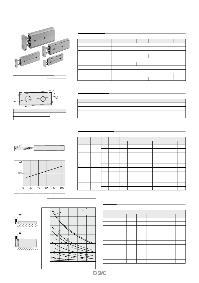
Specifications
Fluid
Proof pressure
Maximum operating pressure
Minimum operating pressure
Ambient and fluid temperature
Piston speed
Cushion
Stroke adjustable range
Port size
Allowable kinetic energy
Bore size (mm)
Air (Non-lube)
1.05 MPa
0.7 MPa
–10 to 60°C (No freezing)
30 to 700 mm/s
M5 x 0.8
0.05 MPa
0 to –5 mm compared to the standard stroke
Standard Stroke
CXSJ6
CXSJ10
CXSJ15
CXSJ20, 25, 32
Model Standard stroke
10, 20, 30, 40, 50
10, 20, 30, 40, 50, 75
10, 20, 30, 40, 50, 75, 100
Long stroke (-XB11)
—
80 to 150
110 to 150
110 to 200
(mm)
6
0.15 MPa
M3 x 0.5
10 15 20 25 32
Rc (NPT, PF) 1/8
0.1 MPa
30 to 800 mm/s 30 to 600 mm/s
Rubber bumper on both ends
Theoretical Output
0.1
—
—
15.7
10.0
35.3
25.2
62.8
47.1
98.2
75.6
161
121
0.2
11.2
6.2
31.4
20.0
70.6
50.4
126
94.2
196
151
322
241
0.3
16.8
9.3
47.1
30.0
106
75.6
188
141
295
227
482
362
0.4
22.4
12.4
62.8
40.0
141
101
251
188
393
302
643
482
0.5
28.0
15.5
78.5
50.0
177
126
314
236
491
378
804
603
0.6
33.6
18.6
94.2
60.0
212
151
377
283
589
454
965
724
0.7
39.2
21.7
110
70.0
247
176
440
330
687
529
1126
844
0.15
8.4
4.6
—
—
—
—
—
—
—
—
—
—
Operating pressure (MPa)
(N)
Operating
direction
Piston area
(mm
2
)
56
31
157
100
353
252
628
471
982
756
1608
1206
OUT
IN
OUT
IN
OUT
IN
OUT
IN
OUT
IN
OUT
IN
Rod size
(mm)
Bore size
(mm)
4
6
8
10
12
16
Note) Theoretical output (N) = Pressure (MPa) x Piston area (mm
2
)
CXSJ6
CXSJ10
CXSJ15
CXSJ20
CXSJ25
CXSJ32
Note) For axial piping of CXSJ6P- and CXSJ10P-, please add the
following weight. CXSJ6P-: 0.009 kg, CXSJ10P-: 0.014 kg
0.016 J 0.064 J 0.095 J 0.17 J 0.27 J 0.32 J
CXSJ Series
Maximum Load Mass
When the cylinder is mounted as shown in the diagrams below, the
maximum load mass W should not exceed the values illustrated in the
graph.
Operating Conditions
Non-rotating Accuracy
CXSJ6 to 32
Deflection at the Plate End
Non-rotating accuracy θ° without a load should
be less than or equal to the value provided in
the table below as a guide.
An approximate plate-end deflection X without
a load is shown in the graph below.
Bore size (mm)
CXSJM (Slide bearing)
CXSJL
(Ball bushing bearing)
ø6 to ø32
±0.1°
Housing
Plate
Extended rod
Deflection
X mm
Deflection X (mm)
Stroke (mm)
738
A
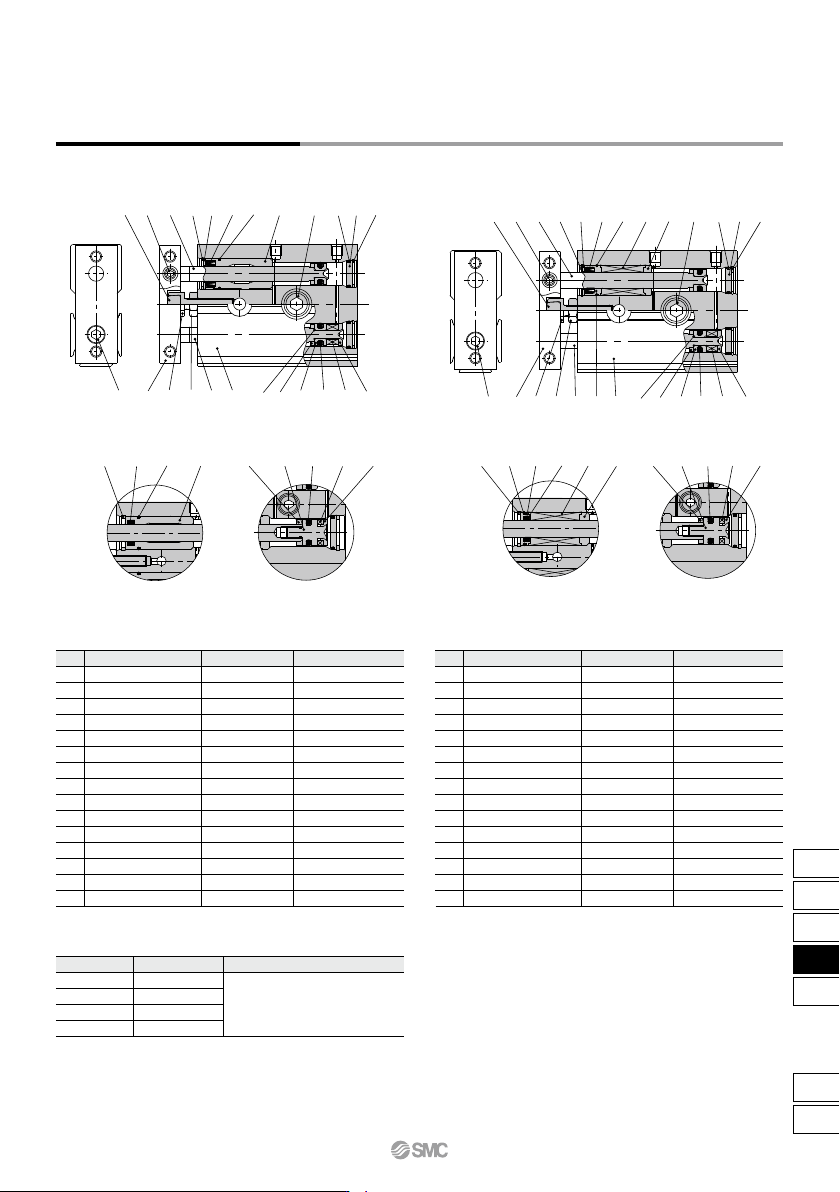
CXSJM (Slide bearing) CXSJL (Ball bushing bearing)
Piston rod B-side piston
Rod cover
CXSJL6
CXSJL10
CXSJM6
CXSJM10
Piston rod B-side piston
Rod cover
!5t@0@3r!9!8@1@2w!4!2
!3 y !0 !1 e q @8 !6 u !7 o i
!5t@0@3@4@5!9!8@1@2@6!4!2
!3 y !0 !1 @7 r q @8 !6 u !7 o i
r!9!8@2 !6 @9 !7 o i @4@5!8r!9@2 !6 @9 !7 o i
Construction: Standard Piping
∗ Seal kit includes !7, !8, and @0. Order the seal kit, based on each bore size.
∗ Since the seal kit does not include a grease pack, order it separately.
Grease pack part no.: GR-S-010 (10 g)
Replacement Parts/Seal Kit
Component Parts: Standard Piping
No. Description
Housing
Piston rod A
Piston rod B
Rod cover
Head cover
Plate
Piston A
Piston B
Magnet
Bumper bolt
Hexagon nut
Bumper
Hexagon socket head cap screw
Hexagon socket head set screw
Retaining ring
Material
Aluminum alloy
Carbon steel
Carbon steel
Aluminum bearing alloy
Aluminum alloy
Aluminum alloy
Aluminum alloy
Aluminum alloy
—
Carbon steel
Carbon steel
Urethane
Chromium steel
Chromium steel
Special steel
Note
Hard anodized
Hard chromium electroplated
Hard chromium electroplated
Anodized
Glossy, self-coloring hard anodized
Chromated
Chromated
Nickel plated
Zinc chromated
Zinc chromated
Zinc chromated
Phosphate coated
1
2
3
4
5
6
7
8
9
10
11
12
13
14
15
No. Description
Bumper B
Piston seal
Rod seal
O-ring
O-ring
Seal retainer
Retaining ring B
Bolt holder
Bearing spacer
Ball bushing
Piston rod A
Piston rod B
O-ring
Piston C
Bumper holder
Material
Urethane
NBR
NBR
NBR
NBR
Stainless steel
Special steel
Stainless steel
Aluminum bearing alloy
—
Special steel
Special steel
NBR
Stainless steel
Resin
Note
Phosphate coated
Hard chromium electroplated
Hard chromium electroplated
16
17
18
19
20
21
22
23
24
25
26
27
28
29
30
Seal kit no.
CXSJM6-PS
CXSJL6-PS
CXSJM10-PS
CXSJL10-PS
Model
Contents
Set of nos. above !7, !8, and @0
CXSJM6
CXSJL6
CXSJM10
CXSJL10
Note) Stainless steel for CXSJM6.
Note)
Note)
CXSJ Series
Dual Rod Cylinder
Compact Type
739
CX2
CXW
CXT
CXSJ
CXS
D-
-X
CXSJ