6-2-2-p0723-0782-cxsj_en.pdf - 第26页
C D A B D-A9 (Reed switch) D-M9 W D-M9 D-M9 A (Solid state switch) D-M9 V D-M9 WV D-M9 AV (Solid state switch) D 1 D 2 C 2 C 1 C 3 B 1 A 1 A B C D D-A9 (Reed switch) D-M9 (Solid state switch) D-M9 W D…
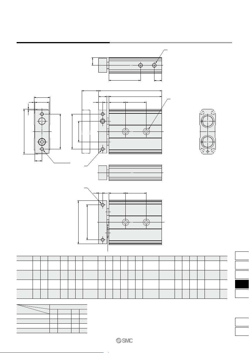
A
54
62
73
94
B
19
24
29
37
C
52
60
71
92
D
17
22
27
35
E
8.5
11
13.5
17.5
G
42
50
60
75
H
25
29
35
45
I
5
6
6
8
J
10
12
12
16
K
2.5
4.5
4.5
4
L
20
25
30
30
NN
ø8
ø10
ø12
ø16
Q
9.5
12
14.5
18.5
R
38
45
46
56
T
9
9
9
10
MF
2 x M5 x 0.8
2 x M5 x 0.8
2 x M6 x 1.0
2 x M6 x 1.0
ZZ
70
84
87
100.5
15
20
25
32
15
20
25
32
Bore size (mm)
2 x 2 x ø4.3 through
2 x 2 x ø8 counterbore
with depth 4.3
2 x 2 x ø5.5 through
2 x 2 x ø9.5 counterbore
with depth 5.3
2 x 2 x ø6.5 through
2 x 2 x ø11 counterbore
with depth 6.3
2 x 2 x ø6.5 through
2 x 2 x ø11 counterbore
with depth 6.3
N
2 x M4 x 0.7
with thread
depth 6
2 x M4 x 0.7
with thread
depth 6
2 x M5 x 0.8
with thread
depth 7.5
2 x M5 x 0.8
with thread
depth 7.5
U
2 x M5 x 0.8
with thread
depth 4
2 x M5 x 0.8
with thread
depth 4
2 x M5 x 0.8
with thread
depth 4
2 x Rc1/8
with thread
depth 5
10, 20
25
30
30
40
30, 40, 50
35
40
40
50
75
45
60
60
70
100
55
60
60
70
Z
Symbol
Stroke
Bore size (mm)
SS
57.5
67.5
70.5
80.5
Dimensions: ø15 to 32 Standard Piping
Stroke
R
T
H
(G)
(G)
C
NN
(I )
A
G
± 0.2
M
F
(Through)
N
I
J
K
SS + Stroke
L
Z
ZZ + Stroke
1
1
D
B
E
Q
(L) (Z)
U
N
CXSJ Series
Dual Rod Cylinder
Compact Type
745
CX2
CXW
CXT
CXSJ
CXS
D-
-X
CXSJ
C
D
A
B
D-A9
(Reed switch)
D-M9W
D-M9
D-M9A
(Solid state switch)
D-M9V
D-M9WV
D-M9AV
(Solid state switch)
D
1
D
2
C
2
C1
C3
B
1
A1
A
B
C
D
D-A9 (Reed switch)
D-M9 (Solid state switch)
D-M9W
D-M9A
D-A9V (Reed switch)
D-M9V (Solid state switch)
D-M9WV
D-M9AV
A
1
C
1
C3
C2
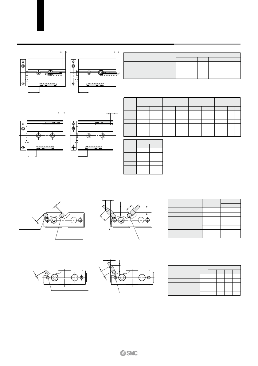
Electrical entry direction:
Inward
Electrical entry direction:
Outward
D-A9V
(Reed switch)
CXSJ6, 10
CXSJ6,10
CXSJ15 to 32
CXSJ15 to 32
Auto switch mounting dimensions
Symbol
A1
A1
C1
C2
C3
15 20 25
1
2
5.5
4.5
1
1
2
5.5
4.5
—
1
2
5.5
4.5
—
1
2
5.5
4.5
—
32
D-M9, D-M9W
D-M9A
D-A9V
D-M9WV
D-M9AV
Auto switch model
(mm)
(mm)
D-A9, D-A9V
D-M9, D-M9V
D-M9A, D-M9AV
D-M9W, D-M9WV
Auto switch model
Bore size
Operating Range
Auto Switch Proper Mounting Position
6
5
2.5
10
6
3
15
6
3.5
20
7.5
4.5
25
8
4.5
32
9
5
A
15.5
25.5
31.5
39
40
49
B
—
—
6
9
11
11.5
C
13.5
23.5
29.5
37
38
47
D
5.5
3
4
7
9
9.5
A
15.5
25.5
31.5
39
40
49
B
—
—
6
9
11
11.5
C
11
21
27
34.5
35.5
44.5
D
8
5.5
1.5
4.5
6.5
7
A
19.5
29.5
35.5
43
44
53
B
0.5
3
10
13
15
15.5
C
9.5
19.5
25.5
33
34
43
D
9.5
7
0
3
5
5.5
6
10
15
20
25
32
Bore size
(mm)
D-M9
, D-M9
W
D-M9
AV
D-A93D-A90, D-A96
A
19.5
29.5
35.5
43
44
53
B
0.5
3
10
13
15
15.5
C
7.5
17.5
23.5
31
32
41
D
11.5
9
2
5
7
7.5
6
10
15
20
25
32
Bore size
(mm)
D-M9A
A
19.5
29.5
35.5
43
44
53
B
0.5
3
10
13
15
15.5
C
11.5
21.5
27.5
35
36
45
D
7.5
5
2
5
7
7.5
D-M9V, D-M9WV
Bore size
∗ The operating ranges are provided as guidelines including hystereses and are not
guaranteed values (assuming approximately ±30% variations).
They may vary significantly with ambient environments.
Symbol
A1
B1
B1
C1, D1
C2, C3, D2
C1, D1
C2, C3, D2
6
1
1
2
5.5
4
8
6
1
1
2
5.5
4
8
6
10
Bore size
D-A9
D-M9,
D-M9W
D-M9A
D-A9V
D-M9V, D-M9WV
D-M9AV
Auto switch model
(mm)
Auto Switch Proper Mounting Position for Stroke End Detection
Note 1) ø6: D-A90, A96, A93, F9BA
ø10: D-A90, A96, A93
Only outward electrical entry (D dimen-
sion) is available.
Note 2) Minus value in D column (ø15, ø20, ø25,
ø32) means that the auto switches are to
be mounted beyond the cylinder body
edges.
Note 3) When setting an auto switch, confirm the
operation and adjust its mounting position.
CXSJ Series
Auto Switch Mounting
746
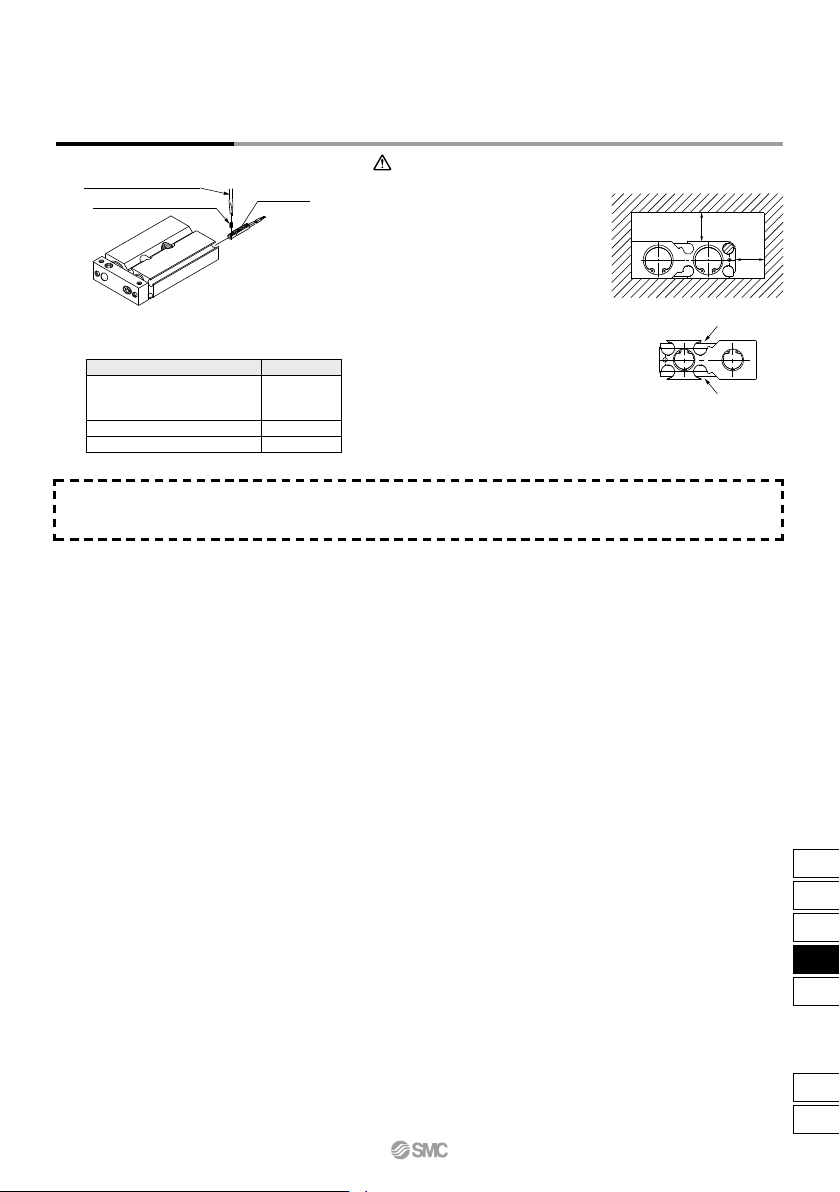
Watchmaker’s screwdriver
Auto switch mounting screw
Auto switch
• Use a watchmaker’s screwdriver with
a handle 5 to 6 mm in diameter when
tightening the auto switch mounting
screw.
Auto Switch Mounting
10 mm
10 mm
Tightening Torque of Auto Switch Mounting Screw
(N·m)
q Avoid proximity to magnetic objects.
When magnetic substances such as iron
(including flange brackets) are in close
proximity to an auto switch cylinder (auto
switch mounting side), be sure to provide a
clearance between the magnetic substance
and the cylinder body as shown in the
drawing below. If the clearance is less than
10 mm, the auto switch may not function
properly.
w For CXSJ6/10, the switch cannot be
attached or detached from the plate
side if the middle groove (indicated
by arrows in the figure on the right) is
used. (It will interfere with the bumper
bolt at the end of the groove.)
Caution
Other than the applicable auto switches listed in “How to Order,” the following auto switches can be mounted.
∗ Normally closed (NC = b contact) solid state auto switches (D-M9E(V)) are also available. For details, refer to page 1592-1.
Auto Switch Mounting CXSJ Series
D-M9(V)
D-M9W(V)
D-A93
D-M9A(V)
D-A9(V) (Excludes the D-A93)
Auto switch model Tightening torque
0.05 to 0.15
0.05 to 0.10
0.10 to 0.20
747
CX2
CXW
CXT
CXSJ
CXS
D-
-X
CXSJ
B