6-2-2-p0723-0782-cxsj_en.pdf - 第29页
Dual Rod Cylinder Basic Type CXS Series ø 6, ø 10, ø 15, ø 20, ø 25, ø 32 CXS M Y7BW 100 20 M L 15, 20 25, 32 10 Without auto switch (Built-in magnet) Z76 Z73 Y59A Y7P Y59B Y7NW Y7PW Y7BW Y7BA ∗∗ Y69A Y7PV Y69B Y7NWV Y7P…
A
A
Section A
–
A
Bolt holder (movable)
B
B
Section B
–
B
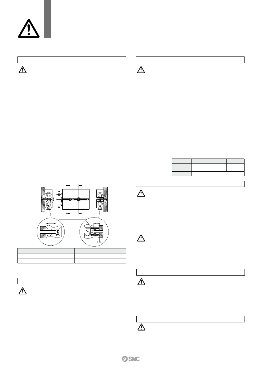
Approx. 0.5 or less
L2
L1
Bore size (mm)
Part no.
Qty.
6, 10, 15
CXS10-34A
28747
20, 25
CXS20-34A
28749
1
32
CXS32-34A
28751
CXSJ Series
Specific Product Precautions
Be sure to read this before handling the products.
Refer to back page 50 for Safety Instructions and pages 3 to 12 for Actuator and
Auto Switch Precautions.
1. Make sure that the surface on which the cylinder is
to be mounted is flat (reference value for flatness:
0.05 or less).
Dual-rod cylinders can be mounted from 3 directions, however,
make sure that the surface on which the cylinder is to be
mounted is flat (reference value for flatness: 0.05 or less).
Otherwise, the accuracy of the piston rod operation is not
achieved, and malfunctioning can occur.
2. The piston rod must be retracted when mounting
the cylinder.
Scratches or gouges in the piston rod may lead to damaged
bearings and seals and cause malfunctions or air leakage.
3. CXSJ (ø6, ø10)
Adjust the bolt holder using a hexagon wrench 3 mm in width
across flats so that it does not protrude from the cylinder
surface (approx. 0.5 mm depth from the cylinder surface to the
top of the holder). If the bolt holder is not properly adjusted, it
can interfere with the switch rail, hindering the auto switch
mounting. The required length of the mounting bolt for a bolt
holder and mounting hole in the rod cover side varies
depending on the bearing surface position for the mounting
bolt. Refer to dimensions L
1 and L2 provided below to select
the appropriate mounting bolt length.
Mounting
Caution
Be sure to mount the cylinder to the bolt holder. If it is oper-
ated without using the bolt holder, the bolt holder may drop.
CXSJ6
CXSJ10
L1
(mm)
5
5
L
2 (mm)
8.4
9.5
Applicable mounting bolt size
M3
M3
1.
For axial piping, the side port of the standard cylinder is
plugged. However, a plugged port can be switched according
to the operating conditions. When changing the port position,
use the removed plug or a new plug. If reusing the removed
plug, apply sealant, etc., before reassembly. If using a new M5
plug, apply a thin layer of grease all the way around the male
thread before use. In addition, clear any foreign matter
adhered to the port the plug was removed from before piping.
After reassembly, be sure to check for air leakage before
operating the product.
Plug part no.: (ø6) MTS08-08-P6830
(ø10) CXS10-08-R8601
Piping
Caution
1. After adjusting the stroke, make sure to tighten the
hexagon nut to prevent it from loosening.
Dual-rod cylinders have a bolt to adjust 0 to –5 mm strokes on
the retracted end (IN).
Loosen the hexagon nut to adjust the stroke; however, make
sure to tighten the hexagon nut after making an adjustment.
2. Never operate a cylinder with its bumper bolt re-
moved. Also, do not attempt to tighten the bumper
bolt without using a nut.
If the bumper bolt is removed, the piston hits the head cover
causing damage to the cylinder. Therefore, do not use a cylin-
der without a bumper bolt.
Furthermore, if the bumper bolt is tightened without a nut, the
piston seal is caught in the leveled part, damaging the seal.
3. A bumper at the end of the bumper bolt is replace-
able.
In case of a missing bumper, or a bumper has a permanent
settling, use the
right part
numbers for
ordering.
Stroke Adjustment
Caution
1. Never use a cylinder with its plate removed.
When removing the hexagon socket head cap screw on the
end plate, the piston rod must be secured to prevent from ro-
tating. However, if the sliding parts of the piston rod are
scratched and gouged, a malfunction may occur.
2.
When disassembling and reassembling the cylinder,
contact SMC or refer to the separate operation manual.
Disassembly and Maintenance
1. Take precautions when your hands are near the
plate and housing.
When the cylinder is operated, take extra precautions to avoid
getting your hands and fingers caught between the plate and
housing, that can cause a bodily injury.
Warning
Caution
1.
Do not operate the cylinder in a pressurized environment.
The pressurized air may flow inside the cylinder due to its construction.
2.
Do not use as a stopper. This may cause malfunction.
When using as a stopper, select a stopper cylinder (RS
series) or a compact guide cylinder (MGP series).
Operating Environment
Caution
1. A sudden extension may occur with CXSJ6.
CXSJ6 has a low internal volume and sudden extension/erratic
movement may occur particularly when it is used at low speed.
This sudden extension can be mitigated by combining the use of
meter-in and meter-out speed controllers.
Speed Adjustment
Caution
748
c
Dual Rod Cylinder
Basic Type
CXS Series
ø6, ø10, ø15, ø20, ø25, ø32
CXS M Y7BW10020
M
L
15, 20
25, 32
10
Without auto switch (Built-in magnet)
Z76
Z73
Y59A
Y7P
Y59B
Y7NW
Y7PW
Y7BW
Y7BA
∗∗
Y69A
Y7PV
Y69B
Y7NWV
Y7PWV
Y7BWV
Z80
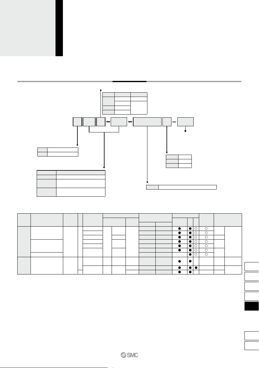
How to Order
Thread type
Symbol Bore size
ø6 to ø20
ø25,ø32
Type
M thread
Rc 1/8
NPT 1/8
G 1/8
Nil
TN
TF
Bearing type
Slide bearing
Ball bushing bearing
2 pcs.
1 pc.
“n” pcs.
Number of auto switches
Nil
S
n
Auto switch
Nil
∗ For the applicable auto switch model, refer to the table below.
Bore size
6
Standard stroke (mm)
10, 20, 30, 40, 50
10, 15, 20, 25, 30, 35, 40, 45,
50, 60, 70, 75
10, 15, 20, 25, 30, 35, 40, 45,
50, 60, 70, 75, 80, 90, 100
Bore size/Stroke (mm)
Applicable Auto Switches/Refer to pages 1119 to 1245 for further information on auto switches.
Made to Order
Refer to page 750 for details.
Special functionType
Electrical
entry
Indicator light
Wiring
(Output)
Water resistant
(2-color indicator)
Diagnostic indication
(2-color indicator)
Yes
None
Yes
Grommet
Grommet
3-wire (NPN)
3-wire (PNP)
2-wire
3-wire (NPN)
3-wire (PNP)
2-wire
2-wire
3-wire
(NPN equivalent)
Reed
auto switch
Solid state auto switch
—
—
AC
DC
24 V 12 V
5 V
5 V, 12 V
12 V
5 V, 12 V
12 V
24 V
100 V
100 V or less
Load voltage
Auto switch model
Perpendicular
In-line
—
—
—
—
—
—
—
Lead wire length (m)
∗
0.5
(Nil)
3
(L)
5
(Z)
—
—
—
—
—
—
IC
circuit
IC
circuit
IC
circuit
IC circuit
Applicable load
—
—
—
—
Pre-wired
connector
Relay,
PLC
Relay,
PLC
• Since there are other applicable auto switches than listed, refer to page 758 for details.
• For details about auto switches with pre-wired connector, refer to pages 1192 and 1193.
• Auto switches are shipped together (not assembled).
∗ Solid state auto switches marked with “” are produced upon receipt of order.
∗∗ Water resistant type auto switches can be mounted on the above models, but in such case SMC cannot guarantee water resistance.
Consult with SMC regarding water resistant types with the above model numbers.
∗ Lead wire length symbols: 0.5 m ·········· Nil (Example) Y59A
3 m ·········· L (Example) Y59AL
5 m ·········· Z (Example) Y59AZ
749
CX2
CXW
CXT
CXSJ
CXS
D-
-X
CXS
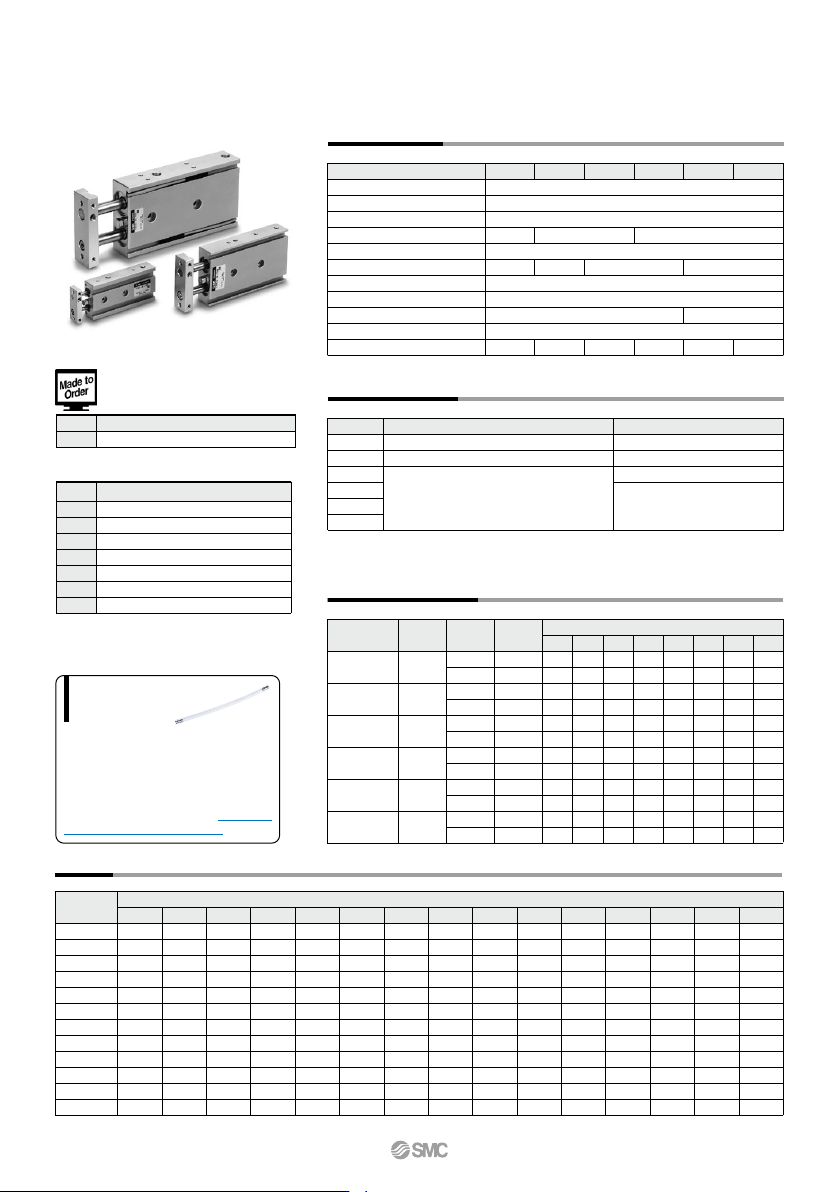
When operating an actuator with a small diam-
eter and a short stroke at a high frequency, the
dew condensation (water droplet) may occur
inside the piping depending on the conditions.
Simply connecting the moisture control tube to
the actuator will prevent dew condensation
from occurring. For details, refer to the IDK se-
ries in the Best Pneumatics No. 6.
Moisture
Control Tube
IDK Series
-X593
Without plate
Symbol
Specifications
Made to Order: Individual
Specifications
(For details, refer to page 759.)
Weight
Standard Stroke
CXSM 6
CXSL 6
CXSM10
CXSL 10
CXSM15
CXSL 15
CXSM20
CXSL 20
CXSM25
CXSL 25
CXSM32
CXSL 32
10
0.081
0.081
0.15
0.15
0.25
0.27
0.40
0.43
0.61
0.62
1.15
1.16
15
—
—
0.16
0.16
0.265
0.285
0.42
0.445
0.635
0.645
1.19
1.205
20
0.095
0.095
0.17
0.17
0.28
0.30
0.44
0.46
0.66
0.67
1.23
1.25
25
—
—
0.18
0.18
0.29
0.31
0.46
0.48
0.69
0.70
1.275
1.295
30
0.108
0.108
0.19
0.19
0.30
0.32
0.48
0.50
0.72
0.73
1.32
1.34
35
—
—
0.20
0.20
0.315
0.335
0.495
0.515
0.745
0.755
1.36
1.38
40
0.122
0.122
0.21
0.21
0.33
0.35
0.51
0.53
0.77
0.78
1.40
1.42
50
0.135
0.135
0.23
0.23
0.36
0.38
0.55
0.57
0.83
0.84
1.49
1.51
45
—
—
0.22
0.22
0.345
0.365
0.53
0.55
0.80
0.81
1.45
1.465
60
—
—
0.25
0.25
0.39
0.41
0.585
0.605
0.89
0.895
1.58
1.595
70
—
—
0.27
0.27
0.42
0.44
0.62
0.64
0.95
0.955
1.665
1.68
75
—
—
0.28
0.28
0.435
0.455
0.64
0.66
0.97
0.98
1.71
1.72
80
—
—
—
—
0.45
0.47
0.66
0.68
0.995
1.005
1.755
1.765
90
—
—
—
—
0.48
0.50
0.70
0.715
1.06
1.065
1.84
1.855
100
—
—
—
—
0.51
0.53
0.74
0.75
1.10
1.11
1.93
1.94
CXS6
CXS10
CXS15
CXS20
CXS25
CXS32
15
6 20 25 32
0.1
—
—
15.7
10.0
35.3
25.2
62.8
47.1
98.2
75.6
161
121
0.2
11.2
6.2
31.4
20.0
70.6
50.4
126
94.2
196
151
322
241
0.3
16.8
9.3
47.1
30.0
106
75.6
188
141
295
227
482
362
0.4
22.4
12.4
62.8
40.0
141
101
251
188
393
302
643
482
0.5
28.0
15.5
78.5
50.0
177
126
314
236
491
378
804
603
0.6
33.6
18.6
94.2
60.0
212
151
377
283
589
454
965
724
0.7
39.2
21.7
110
70.0
247
176
440
330
687
529
1126
844
0.15
8.4
4.6
—
—
—
—
—
—
—
—
—
—
56
31
157
100
353
252
628
471
982
756
1608
1206
OUT
IN
OUT
IN
OUT
IN
OUT
IN
OUT
IN
OUT
IN
4
6
8
10
12
16
CXS6
CXS10
CXS15
CXS20
CXS25
CXS32
60, 70, 75, 80, 90, 100
80, 90, 100, 110, 120, 125, 150
110, 120, 125, 150
110, 120, 125, 150, 175, 200
CXS Series
Specifications
0.095 J
0.0023 J 0.064 J 0.17 J 0.27 J 0.32 J
(mm)
(N)
Theoretical Output
Made to Order Specifications
Click here for details
(kg)
Bore size (mm)
Fluid
Proof pressure
Maximum operating pressure
Minimum operating pressure
Ambient and fluid temperature
Piston speed
Cushion
Stroke adjustable range
Port size
Bearing type
Allowable kinetic energy
Air (Non-lube)
1.05 MPa
0.7 MPa
–10 to 60°C (No freezing)
10
30 to 800 mm/s
Slide bearing, Ball bushing bearing (Same dimensions for both)
30 to 700 mm/s
Rubber bumper
0 to –5 mm compared to the standard stroke
30 to 600 mm/s
Rc 1/8
0.1 MPa 0.05 MPa
0.15 MPa
30 to 300 mm/s
M5 x 0.8
Model
Standard stroke
Long stroke
10, 15, 20, 25, 30, 35, 40, 45, 50,
60, 70, 75, 80, 90, 100
10, 20, 30, 40, 50
10, 15, 20, 25, 30, 35, 40, 45, 50, 60, 70, 75
∗ Refer to “Made to Order Specifications” for stroke which exceeds the standard stroke length.
Non-standard strokes for a size ø6 cylinder are available as a special order.
Operating pressure (MPa)
Operating
direction
Piston area
(mm
2
)
Rod size
(mm)
Model
Note) Theoretical output (N) = Pressure (MPa) x Piston area (mm
2
)
Model
Standard stroke (mm)
-XB6
-XB9
-XB11
-XB13
-XB19
-XC22
-XC85
Symbol
Specifications
Heat resistant cylinder (–10 to 150°C)
Low speed cylinder (10 to 50 mm/s)
Long stroke type
Low speed cylinder (5 to 50 mm/s)
High speed specification
Fluororubber seals
Grease for food processing equipment
750
B