6-2-2-p0723-0782-cxsj_en.pdf - 第43页
CXSM/With air cushion Construction CXSL/With air cushion Component Parts: CXSM No. Description Housing Piston rod A Piston rod B Rod cover Plate Piston A Piston B Bumper B Magnet Bumper bolt Hexagon nut Bumper Hexagon so…
Weight
628
471
982
756
1608
1206
0.2
126
94.2
196
151
322
241
0.3
188
141
295
227
482
362
0.4
251
188
393
302
643
482
0.5
314
236
491
378
804
603
0.6
377
283
589
454
965
724
0.7
440
330
687
529
1126
844
0.1
62.8
47.1
98.2
75.6
161
121
OUT
IN
OUT
IN
OUT
IN
10
12
16
20
0.50
0.52
—
—
—
—
25
0.52
0.54
0.78
0.79
1.48
1.51
30
0.54
0.56
0.80
0.81
1.53
1.55
35
0.56
0.58
0.82
0.83
1.575
1.60
40
0.58
0.60
0.84
0.85
1.62
1.64
45
0.60
0.62
0.86
0.87
1.67
1.69
50
0.62
0.64
0.88
0.89
1.72
1.74
60
0.66
0.68
0.92
0.93
1.82
1.84
70
0.70
0.72
0.96
0.97
1.92
1.94
75
0.715
0.735
0.98
0.99
1.96
1.98
80
0.735
0.755
1.00
1.01
2.06
2.08
90
0.755
0.775
1.04
1.05
2.14
2.16
100
0.815
0.835
1.08
1.09
2.20
2.22
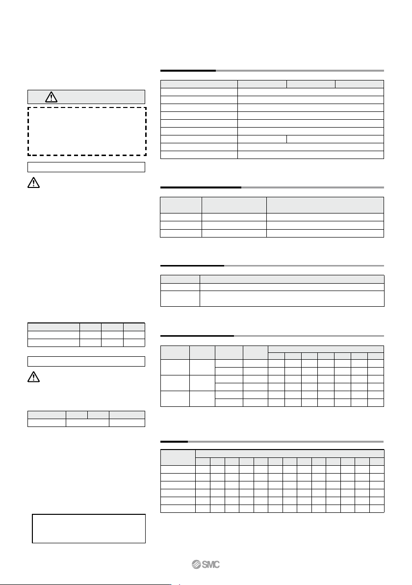
Specifications
32
5.9
5.7
5.6
0.40
0.75
1.0
20
25
32
Cushion Needle Adjustment
(N)
2520
Precautions
Be sure to read this before handling
the products.
Refer to back page 50 for Safety
Instructions and pages 3 to 12 for
Actuator and Auto Switch Precautions.
Selection
Caution
Caution
1.
Operate the cylinder until the stroke end.
If the stroke is restricted by the external
stopper and clamp workpiece, effective
cushioning and noise reduction will not be
achieved.
2. Adjust the cushion needles to absorb
the kinetic energy during the cushion
stroke so that excessive kinitic energy
does not remain when the piston reach-
es the stroke end.
If the piston reaches the stroke end with ex-
cessive kinetic energy remaining (more
than the values given in table (1) below)
due to an improper adjustment, excessive
impact will occur, causing damage to ma-
chinery.
Table (1) Allowable Value at Piston Impact
Bore size (mm)
Piston speed (mm/s)
Kinetic energy (J)
25
50 to 600
0.27
20
50 to 700
0.17
32
50 to 600
0.32
1.Keep the adjusting range for the cush-
ion needle between the fully closed
position and the rotations shown below.
Bore size (mm)
Rotations
2520
32
3 rotations or less
2.5 rotations or less
Use a 3 mm flat head watchmakers screw-
driver to adjust the cushion needles to the
fully closed position, as this will cause dam-
age to the seals. The adjusting range for the
cushion needles must be between the fully
closed position and the open position rang-
es indicated in the table above. A retaining
mechanism prevents the cushion needles
from slipping out; however, they may spring
out during operation if they are rotated be-
yond the ranges shown above.
Precautions for selection standard, mount-
ing, piping, and operating environment are
same as for the standard series.
Fluid
Proof pressure
Maximum operating pressure
Minimum operating pressure
Ambient and fluid temperature
Piston speed
Port size
Bearing type
Cushion
Bore size (mm)
Air (Non-lube)
1.05 MPa
0.7 MPa
0.1 MPa
–10 to 60°C (No freezing)
50 to 1000 mm/s
M5 x 0.8
Rc 1/8 (NPT 1/8, G 1/8)
Slide bearing, Ball bushing bearing (Same dimensions for both)
Air cushion (Both ends)
Cushion mechanism
Absorbable kinetic energy (J)
Effective cushion length
(mm)
Bore size
(mm)
Standard Stroke
CXS20
CXS25
CXS32
Model
Standard stroke
20, 25, 30, 35, 40, 45, 50, 60, 70, 75, 80, 90, 100
(mm)
25, 30, 35, 40, 45, 50, 60, 70, 75, 80, 90, 100
Theoretical Output
CXS20
CXS25
CXS32
Model
Operating
direction
Operating pressure (MPa)
Rod size
(mm)
Piston area
(mm
2
)
Note) Theoretical output (N) = Pressure (MPa) x Piston area (mm
2
)
Model
CXSM20-A
CXSL20-A
CXSM25-A
CXSL25-A
CXSM32-A
CXSL32-A
Standard stroke (mm)
(kg)
∗ Maximum load mass is the same as the standard type.
CXS Series
762
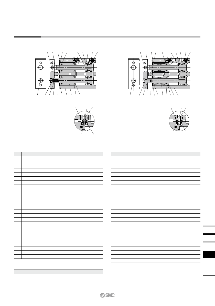
CXSM/With air cushion
Construction
CXSL/With air cushion
Component Parts: CXSM
No. Description
Housing
Piston rod A
Piston rod B
Rod cover
Plate
Piston A
Piston B
Bumper B
Magnet
Bumper bolt
Hexagon nut
Bumper
Hexagon socket head cap screw
Hexagon socket head set screw
Retaining ring
Steel ball
Piston seal
Rod seal
O-ring
O-ring
Cushion needle
Check seal retainer
Check seal
Needle gasket
Check gasket
Material
Aluminum alloy
Carbon steel
Carbon steel
Aluminum bearing alloy
Aluminum alloy
Aluminum alloy
Aluminum alloy
Urethane
—
Carbon steel
Carbon steel
Urethane
Chromium steel
Chromium steel
Special steel
Special steel
NBR
NBR
NBR
NBR
Stainless steel
Copper alloy
NBR
NBR
NBR
Note
Hard anodized
Hard chrome plated
Hard chrome plated
Anodized
Chromated
Chromated
Nickel plated
Zinc chromated
Zinc chromated
Zinc chromated
Phosphate coated
Nickel plated
1
2
3
4
5
6
7
8
9
10
11
12
13
14
15
16
17
18
19
20
21
22
23
24
25
Replacement Parts/Seal Kit
Kit no.
CXS20A-PS
CXS25A-PS
CXS32A-PS
Bore size (mm)
20
25
32
Contents
Component Parts: CXSL
No. Description
Housing
Piston rod A
Piston rod B
Bearing spacer
Ball bushing
Bumper holder
Plate
Piston A
Piston B
Bumper B
Magnet
Bumper bolt
Hexagon nut
Bumper
Hexagon socket head cap screw
Hexagon socket head set screw
Retaining ring
Steel ball
Piston seal
Rod seal
O-ring
O-ring
Cushion needle
Check seal retainer
Check seal
Needle gasket
Check gasket
Material
Aluminum alloy
Special steel
Special steel
Aluminum alloy
—
Aluminum alloy
Aluminum alloy
Aluminum alloy
Aluminum alloy
Urethane
—
Carbon steel
Carbon steel
Urethane
Chromium steel
Chromium steel
Special steel
Special steel
NBR
NBR
NBR
NBR
Stainless steel
Copper alloy
NBR
NBR
NBR
Note
Hard anodized
Hard chrome plated
Hard chrome plated
Anodized
Chromated
Chromated
Nickel plated
Zinc chromated
Zinc chromated
Zinc chromated
Phosphate coated
Nickel plated
1
2
3
4
5
6
7
8
9
10
11
12
13
14
15
16
17
18
19
20
21
22
23
24
25
26
27
∗ Seal kit includes !7, !8 and !9. Order the seal kit, based on each bore size.
∗ Since the seal kit does not include a grease pack, order it separately.
Grease pack part no.: GR-S-010 (10 g)
CXSM: Set of nos. !7, !8 and !9
CXSL: Set of nos. !9, @0 and @1
Close-up of AClose-up of A
CXS Series
Dual Rod Cylinder
With Air Cushion
!3 !2e !1
!0
q r
u
@4
@0
@3
@1
@2
!7
!4
w
!8
o
!6
y
i
A
@5
!5 !9t
!3
!2
ye
!1
o
!0
q
!5
u t
@7
@4
@5
@3
@2
@6
!9
!4
w
@0
!8
r
!6 i
!7
@1
A
763
CX2
CXW
CXT
CXSJ
CXS
D-
-X
CXS
S
20
25
30
35
40
45
50
60
70
75
80
90
100
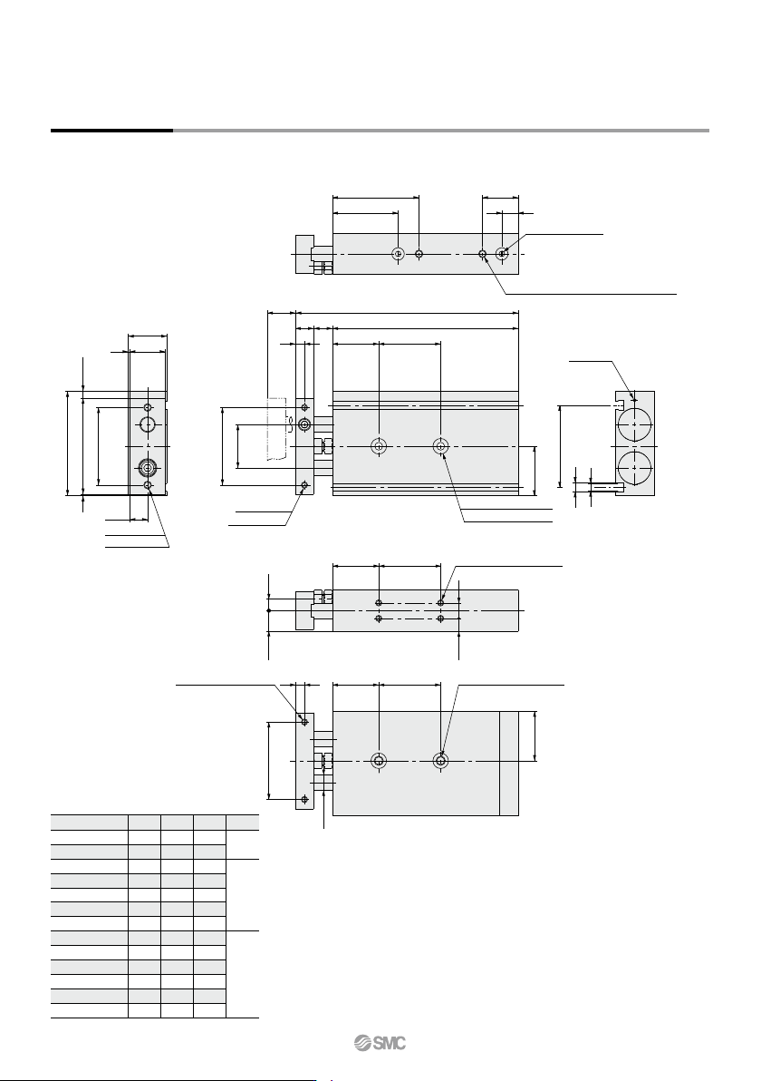
SS
92
97
102
107
112
117
122
132
142
147
152
162
172
ZZ
116
121
126
131
136
141
146
156
166
171
176
186
196
Z
30
40
60
S
Z
SS
ZZ
(Z)
Dimensions: ø20
(Through-hole)
50 ±
0.2
(4.5)
2 x M5 x 0.8
231
25
62
11.5
67.5
1
53.5 19
43
9
2 x M5 x 0.8 thread depth 4.5 (Piping port)
2 x cushion needle
32
2 x ø5.5 through
2 x ø9.5 counterbore depth 5.3
50 ±
0.2
2 x M4 x 0.7
thread depth 6
28
6
12
30
12
30
9.5
7.75
6.512.5
4 x M4 x 0.7 thread depth 5.5
CXS20-20A
CXS20-25A
CXS20-30A
CXS20-35A
CXS20-40A
CXS20-45A
CXS20-50A
CXS20-60A
CXS20-70A
CXS20-75A
CXS20-80A
CXS20-90A
CXS20-100A
Part no.
(mm)
CXS Series
(Steel ball)
5
6.3
53
2 x M6 x 1.0 thread depth 10
2 x M4 x 0.7 thread depth 6
50 ±
0.2
6 (30) (Z)
ø10
(32)
764