6-2-2-p0723-0782-cxsj_en.pdf - 第46页
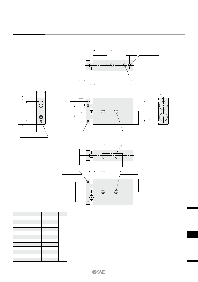
S 25 30 35 40 45 50 60 70 75 80 90 100 SS 112 117 122 127 132 137 147 157 162 167 177 187 ZZ 142 147 152 157 162 167 177 187 192 197 207 217 Z 40 50 70 Z SS ZZ S (Z) 19 11.5 T Dimensions: ø 32 30 8 16 14 44 67.5 23.5 54 …
S
25
30
35
40
45
50
60
70
75
80
90
100
SS
100
105
110
115
120
125
135
145
150
155
165
175
ZZ
124
129
134
139
144
149
159
169
174
179
189
199
Z
30
40
60
(Z)
Z
ZZS
SS
Note) For port threads TN and TF, only the piping port type varies.
Dimensions: ø25
57.5
22
45.5
10
30
1212
6
40
60 ±
0.2
78
281
30
14
81.5
(2.5)
2 x Rc 1/8 thread depth 6.5 (Piping port)
Note)
2 x cushion needle
(Steel ball)
5
6.3
64
2
x
ø6.9 through
2 x ø11 counterbore depth 6.3
thread depth 7.5
2 x M5 x 0.8
35
60 ±
0.2
2 x M6 x 1.0 (Through-hole)
30
138.5
15
9
4 x M5 x 0.8 thread depth 7.5
2 x M8 x 1.25
thread depth 12
2 x M5 x 0.8
thread depth 7.5
(30) (Z)
60 ±
0.2
6
ø12
(40)
CXS25-25A
CXS25-30A
CXS25-35A
CXS25-40A
CXS25-45A
CXS25-50A
CXS25-60A
CXS25-70A
CXS25-75A
CXS25-80A
CXS25-90A
CXS25-100A
Part no.
(mm)
1
CXS Series
Dual Rod Cylinder
With Air Cushion
765
CX2
CXW
CXT
CXSJ
CXS
D-
-X
CXS
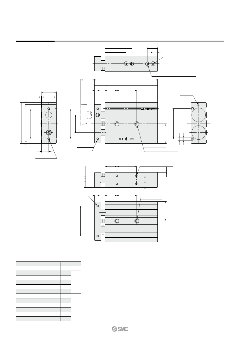
S
25
30
35
40
45
50
60
70
75
80
90
100
SS
112
117
122
127
132
137
147
157
162
167
177
187
ZZ
142
147
152
157
162
167
177
187
192
197
207
217
Z
40
50
70
Z
SS
ZZS
(Z)
19 11.5
T
Dimensions: ø32
308
16 14
44
67.5 23.5
54
10
96
18
361
38
102
(5)
1
49
75 ±
0.2
75 ±
0.2
2 x M6 x 1.0
(Through-hole)
thread depth 8
2 x M5 x 0.8
2 x ø6.9 through
2 x ø11 counterbore depth 6.3
2 x Rc 1/8 thread depth 6.5 (Piping port)
Note)
2 x cushion needle
(Steel ball)
5
76
6.3
4 x M5 x 0.8 thread depth 7.5
30
9 20
CXS32-25A
CXS32-30A
CXS32-35A
CXS32-40A
CXS32-45A
CXS32-50A
CXS32-60A
CXS32-70A
CXS32-75A
CXS32-80A
CXS32-90A
CXS32-100A
Part no.
(mm)
Note) For port threads TN and TF, only the piping port type varies.
CXS Series
2 x M5 x 0.8 thread depth 8
2 x M8 x 1.25
thread depth 12
(30) (Z)8
75 ±
0.2
ø16
(49)
766
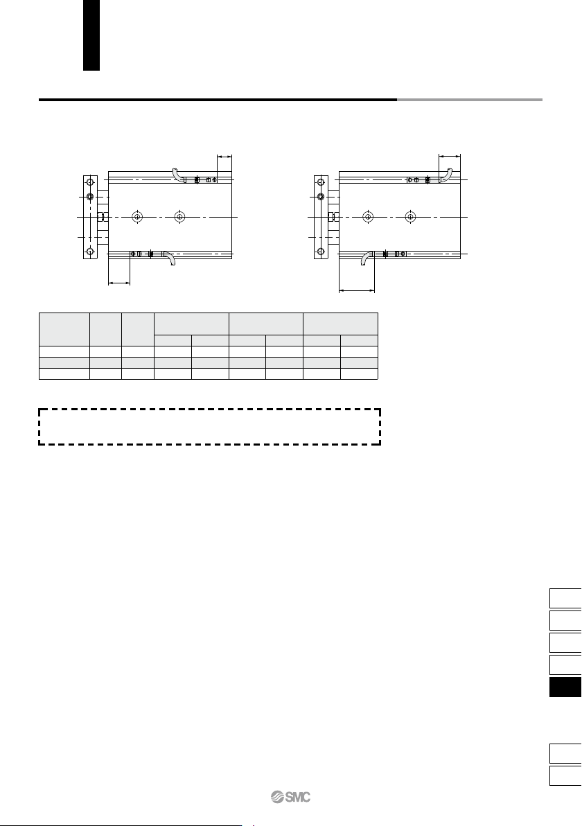
Note) Adjust the auto switch after confirming the operating conditions in the actual setting.
20
25
32
BA
C
36.5(35)
38(36.5)
48.5(47)
40.5
42
52.5
6.5
8
9.5
D
2.5(1)
4(2.5)
5.5(4)
C
38.5
40
50.5
D
4
5.5
7
C
30.5
32
42.5
D
–3.5
–2
–0.5
D
C
B
A
Auto Switch Proper Mounting Position (Detection at Stroke End)
Electrical entry direction: Inward Electrical entry direction: Outward
D-Z7/Z8, D-Y7W
D-Y5, D-Y7
D-Y6, D-Y7V
D-Y7WV
D-Y7BA
Bore size
(mm)
As for auto switch mounting dimensions, auto switch mounting method
and its operating range, those are the same as basic type. Refer to page
758.
CXS Series
Auto Switch Mounting
767
CX2
CXW
CXT
CXSJ
CXS
D-
-X
CXS