6-2-2-p0723-0782-cxsj_en.pdf - 第49页
Whe n ope ratin g an actu ator wi th a smal l dia meter and a shor t str oke at a hig h fr eque ncy, th e dew con dens atio n (water dr ople t) may oc cur ins ide t he pip ing de pend ing on t he co ndit ions . Sim ply c…
CXS M
Y7BW
50 R10
M
L
With end lock for retraction side
Z76
Z73
Y59A
Y7P
Y59B
Y7NW
Y7PW
Y7BW
Y7BA
∗∗
Y69A
Y7PV
Y69B
Y7NWV
Y7PWV
Y7BWV
Z73
Z80
Lead wire length (m)
∗
CXS Series
ø6, ø10, ø15, ø20, ø25, ø32
Wiring
(Output)
100 V or less
Load voltage
Pre-wired
connector
Applicable load
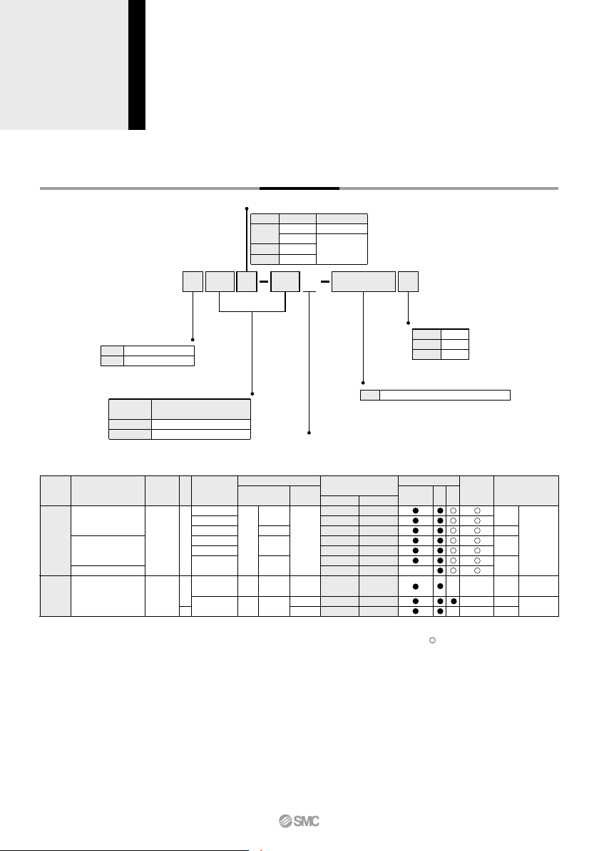
Dual Rod Cylinder
With End Lock for Retraction Side
How to Order
Bearing type
Slide bearing
Ball bushing bearing
Bore size/Stroke (mm)
Bore size
(mm)
10, 20, 30, 40, 50
10, 20, 30, 40, 50, 75, 100
Stroke (mm)
6, 10, 15
20, 25, 32
Number of auto switches
2 pcs.
1 pc.
“n” pcs.
Nil
S
n
Auto switch
Nil
Without auto switch (Built-in magnet)
∗ For the applicable auto switch model, refer to the table below.
Applicable Auto Switches/Refer to pages 1119 to 1245 for further information on auto switches.
Special functionType
Electrical
entry
Indicator light
YesYes
Grommet
Grommet
Reed
auto switch
Solid state auto switch
—
—
Water resistant
(2-color indicator)
Diagnostic indication
(2-color indicator)
None
3-wire (NPN)
3-wire (PNP)
2-wire
3-wire (NPN)
3-wire (PNP)
2-wire
2-wire
3-wire
(NPN equivalent)
AC
DC
5 V
5 V, 12 V
12 V
5 V, 12 V
12 V
24 V
—
24 V 12 V
100 V
—
—
—
—
—
—
Auto switch model
Perpendicular
In-line
0.5
(Nil)
3
(L)
5
(Z)
—
—
—
—
—
—
IC
circuit
IC
circuit
IC
circuit
IC circuit
—
—
—
—
Relay,
PLC
Relay,
PLC
• Since there are other applicable auto switches than listed, refer to page 758 for details.
• For details about auto switches with pre-wired connector, refer to pages 1192 and 1193.
• Auto switches are shipped together (not assembled).
∗ Solid state auto switches marked with “ ” are produced upon receipt of order.
∗∗ Water resistant type auto switches can be mounted on the above models, but in such case SMC cannot guarantee water resistance.
Consult with SMC regarding water resistant types with the above model numbers.
∗ Lead wire length symbols: 0.5 m ·········· Nil (Example) Y59A
3 m ·········· L (Example) Y59AL
5 m ·········· Z (Example) Y59AZ
Thread type
Bore size
ø6 to ø20
ø25, ø32
Type
M thread
Rc 1/8
NPT 1/8
G 1/8
Symbol
Nil
TN
TF
768
When operating an actuator with a small diameter
and a short stroke at a high frequency, the dew
condensation (water droplet) may occur inside the
piping depending on the conditions.
Simply connecting the moisture control tube to the
actuator will prevent dew condensation from oc-
curring. For details, refer to the IDK series in the
Best Pneumatics No. 6.
Moisture
Control Tube
IDK Series
6 10 15 20 25 32
6 10 15 20 25 32
100
—
—
—
—
—
—
0.815
0.835
1.08
1.09
2.2
2.22
75
—
—
—
—
—
—
0.715
0.735
0.98
0.99
1.96
1.98
50
0.165
0.165
0.27
0.27
0.41
0.43
0.62
0.64
0.88
0.89
1.72
1.74
40
0.15
0.15
0.25
0.25
0.38
0.4
0.58
0.60
0.84
0.85
1.62
1.64
30
0.135
0.135
0.225
0.225
0.355
0.375
0.54
0.56
0.8
0.81
1.53
1.55
20
0.12
0.12
0.2
0.2
0.33
0.35
0.5
0.52
0.76
0.77
1.43
1.45
10
0.105
0.105
0.18
0.18
0.3
0.32
0.465
0.485
0.72
0.73
1.33
1.35
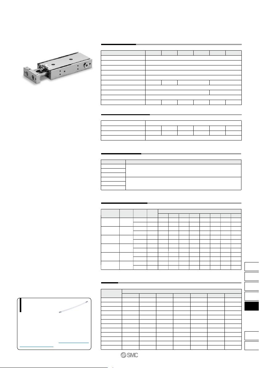
Specifications
∗ Strokes which exceed the standard stroke length will be available as special goods.
Fluid
Proof pressure
Maximum operating pressure
Minimum operating pressure
Ambient and fluid temperature
Piston speed
Cushion
Port size
Bearing type
Allowable kinetic energy
Bore size (mm)
30 to 300mm/s 30 to 800mm/s
30 to 700
mm/s
30 to 600
mm/s
M5 x 0.8
Rc 1/8
0.0023 J 0.064 J 0.095 J 0.17 J 0.27 J 0.32 J
Air (Non-lube)
1.05 MPa
0.7 MPa
0.3 MPa
–10 to 60°C (No freezing)
Bumper is standard on both ends
Slide bearing, Ball bushing bearing (Same dimensions for both)
Lock Specifications
Lock specifications
Bore size (mm)
Maximum holding force (N)
Manual release
Rear end lock
Non-lock type
14.7 98.1 157 235 38239.2
∗ Maximum load mass is the same as the standard type.
Standard Stroke
CXS 6
CXS10
CXS15
CXS20
CXS25
CXS32
Model
Standard stroke
(mm)
10, 20, 30, 40, 50, 75, 100
10, 20, 30, 40, 50
Theoretical Output
56
31
157
100
353
252
628
471
982
756
1608
1206
0.1
—
—
15.7
10.0
35.3
25.2
62.8
47.1
98.2
75.6
161
121
0.15
8.4
4.6
—
—
—
—
—
—
—
—
—
—
0.2
11.2
6.2
31.4
20.0
70.6
50.4
126
94.2
196
151
322
241
0.3
16.8
9.3
47.1
30.0
106
75.6
188
141
295
227
482
362
0.4
22.4
12.4
62.8
40.0
141
101
251
188
393
302
643
482
0.5
28.0
15.5
78.5
50.0
177
126
314
236
491
378
804
603
0.6
33.6
18.6
94.2
60.0
212
151
377
283
589
454
965
724
0.7
39.2
21.7
110
70.0
247
176
440
330
687
529
1126
844
OUT
IN
OUT
IN
OUT
IN
OUT
IN
OUT
IN
OUT
IN
4
6
8
10
12
16
(N)
CXS 6
CXS10
CXS15
CXS20
CXS25
CXS32
Model
Operating
direction
Operating pressure (MPa)
Rod size
(mm)
Piston
area
(mm
2
)
Note) Theoretical output (N) = Pressure (MPa) x Piston area (mm
2
)
Weight
(kg)
CXSM6-R
CXSL6-R
CXSM10-R
CXSL10-R
CXSM15-R
CXSL15-R
CXSM20-R
CXSL20-R
CXSM25-R
CXSL25-R
CXSM32-R
CXSL32-R
Standard stroke (mm)
Model
CXS Series
Dual Rod Cylinder
With End Lock for Retraction Side
769
CX2
CXW
CXT
CXSJ
CXS
D-
-X
CXS
CXS Series
q
6
10
15
20
25
32
CXSRM6-PS
CXSRL6APS
CXSRM10-PS
CXSRL10APS
CXSRM15-PS
CXSRL15APS
CXSRM20-PS
CXSRL20APS
CXSRM25-PS
CXSRL25APS
CXSRM32-PS
CXSRL32APS
e r
!1
y i t o
u !0
w
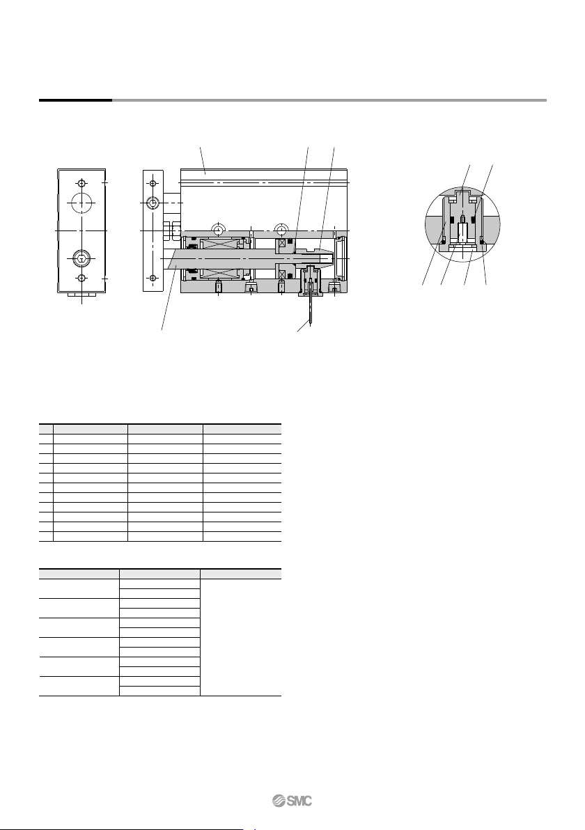
Construction
Component Parts
No.
1
2
3
4
5
6
7
8
9
10
11
Description Material
Aluminum alloy
Carbon steel
NBR
Special steel
Special steel
Aluminum alloy
Special steel
Piano wire
NBR
NBR
Special steel
Note
Hard anodized
Hard chrome plated
Housing
Piston rod B
O-ring
Lock rod
Retaining ring
Lock holder
Lock pin
Lock spring
O-ring
Rod seal
Manual lever
∗ Parts other than those listed above are the same as those for standard type.
Replacement Parts/Seal Kit
Bore size (mm) Kit no. Contents
Includes the kit
components of the seal
kit featured on page
754 plus items o and
!0 from the parts list
above.
∗ Seal kits includes the basic type seal (page 754), o and !0. Order the seal
kit, based on each bore size.
∗ Since the seal kit does not include a grease pack, order it separately.
Grease pack part no.:GR-S-010 (10 g)
770