6-2-2-p0723-0782-cxsj_en.pdf - 第53页
Auto Switch Proper Mounting Position (Detection at Stroke End) 6 10 15 20 25 32 B A C 11.5 (10) 18.5 (17) 26.5 (25) 34 (32.5) 34 (32.5) 44 (42.5) 15.5 22.5 30.5 38 38 48 24.5 22.5 24.5 27 34 39 D 20.5 (19) 18.5 (17) 20.5…
Z
3
KK
ZZ
SS
Z
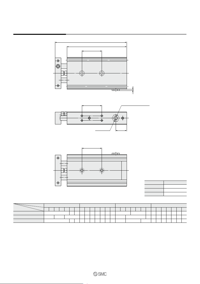
Manual lever insertion ø1.7
Hexagon (
O)
Model
CXS20-R
CXS25-R
CXS32-R
O
Width across flats13
Width across flats16
Width across flats19
(mm)
CXS20-R
CXS25-R
CXS32-R
ZZZSSKK
100
190
197
232
50
140
147
162
30
120
132
142
75
170
172
192
40
130
142
152
20
110
117
132
10
100
107
122
100
22
49
75
27
24.5
34
504030
22
29
2010
24.5 29.5
(mm)
100
214
221
262
50
164
171
192
30
144
156
172
75
194
196
222
40
154
166
182
20
134
141
162
10
124
131
152
100
80
80
7550
60
40
70 90
30
40
50
20
40
60
10
∗ Dimensions other than those listed above are the same as for the standard type.
Model
Symbol
Stroke
Dimensions: ø20, ø25, ø32
CXS Series
Z
772
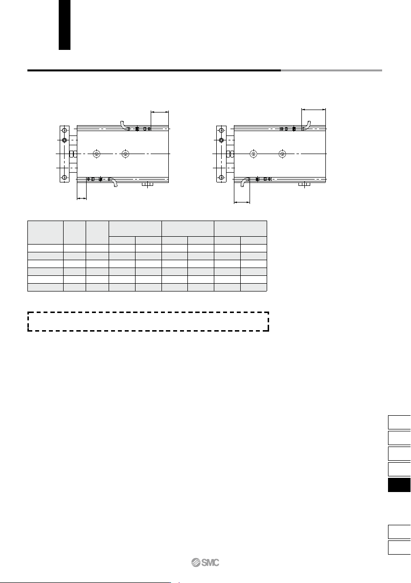
Auto Switch Proper Mounting Position (Detection at Stroke End)
6
10
15
20
25
32
BA
C
11.5 (10)
18.5 (17)
26.5 (25)
34 (32.5)
34 (32.5)
44 (42.5)
15.5
22.5
30.5
38
38
48
24.5
22.5
24.5
27
34
39
D
20.5 (19)
18.5 (17)
20.5 (19)
23 (21.5)
30 (28.5)
35 (33.5)
C
13
20
28
36
36
46
D
22
20
22
24.5
31.5
6.5
C
5.5
12.5
20.5
28
28
38
D
14.5
12.5
14.5
17
24
29
D-Z7/Z8, D-Y7W
D-Y5, D-Y7
D-Y6, D-Y7V
D-Y7WV
D-Y7BAL
Bore size
(mm)
Electrical entry direction: Inward
Electrical entry direction: Outward
A
B
C
D
Note) Adjust the auto switch after confirming the operating conditions in the actual setting.
As for auto switch mounting dimensions, auto switch mounting method and its
operating range, those are the same as basic type. Refer to page 758.
CXS Series
Auto Switch Mounting
773
CX2
CXW
CXT
CXSJ
CXS
D-
-X
CXS
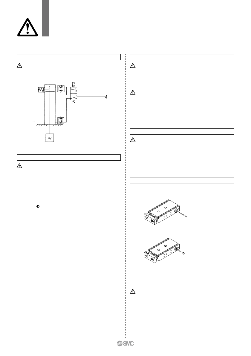
Recommended Pneumatic Circuit Operating Pressure
This is necessary for the proper operation and release of the lock.
Caution
Handling Precautions
Caution
1. Apply a pressure more than 0.3 MPa to the port on the head side.
The pressure is necessary to release the lock.
Caution
Exhaust Speed
1. Locking will occur automatically if the pressure applied to the port
on the head side falls to 0.05 MPa or less. In cases where the
piping on the head side is long and thin, or the speed controller is
separated at some distance from the cylinder port, the exhaust
speed will be reduced. Note that some time may be required for the
lock to engage. In addition, clogging of a silencer mounted on the
solenoid valve exhaust port can produce the same effect.
Caution
Releasing the lock
1. Before releasing the lock, be sure to supply air to the rod side, so
that there is no load applied to the lock mechanism when it is
released. (Refer to the Recommended Pneumatic Circuit.) If the
lock is released when the rod side is in an exhaust state, and with
a load applied to the lock unit, the lock unit may be subjected to an
excessive force and be damaged. Furthermore, sudden movement
of the slide table is extremely dangerous.
Warning
1. Do not use 3 position solenoid valves.
Avoid using in combination with 3 position solenoid valves
(especially closed center metal seal types). If pressure is trapped
in the port on the head side, the cylinder cannot be locked. Even
after being locked, the lock may be released after some time, due
to air leakage from the solenoid valve entering the cylinder.
2. Back pressure is required to release the end lock.
Be sure that air is supplied to the rod side before starting
operation, as shown in the drawing on the left. The lock may not be
released. ( Refer to the section on releasing the lock.)
3. Release the lock when mounting and adjusting the cylinder.
An attempt to mount or adjust a cylinder while it is locked can
damage the lock.
4. Operate with a load ratio of 50% or less.
If the load ratio exceeds 50%, this may cause problems such as
failure of the lock to release, or damage to the lock unit.
5. Do not operate multiple cylinders in synchronization.
Avoid applications in which two or more end lock cylinders are
synchronized to move one workpiece, as one of the cylinder locks
may not be able to release when required.
6. Install speed controllers as they will be meter-out control.
When they are used under meter-in control, the lock may not be
released.
7. Never adjust the retracting stroke using a bumper bolt or
external stopper. The lock will not function.
1. Insert the manual lever and screw it into the lock holder assembly.
If the lever is screwed in sidelong, it may damage the lock spring.
2. To unlock, pull the manual lever in the direction of the arrow.
Release the manual lever to return the cylinder to a ready-to-lock
state.
3.
The manual lever (ø1.6 x 35 L, tip part: M1.6 x 0.35 x 3 L) is included
with the cylinder. If additional manual levers are required, use the
following part number to place an order: CXS06-48BK2777 (for all
series).
Manual Release
Manual release (Non-locking type)
CXS Series
With End Lock for Retraction Side
Specific Product Precautions
Be sure to read this before handling the products.
Refer to back page 50 for Safety Instructions and pages 3 to 12 for Actuator and
Auto Switch Precautions.
Do not use the cylinder while the manual lever is screwed in. It may
damage the lock mechanism.
Caution
774