6-2-2-p0723-0782-cxsj_en.pdf - 第57页
Maximum Load Mass Deflection at the Plate End Non-rotating accuracy Allowable Kinetic Energy Bore size (mm) 6 to 32 ± 0.03 mm CXSWM (Slide bearing) CXSWL (Ball bushing bearing) Bore size (mm) 6 to 32 ± 0.1 ° CXSWM (Slide…
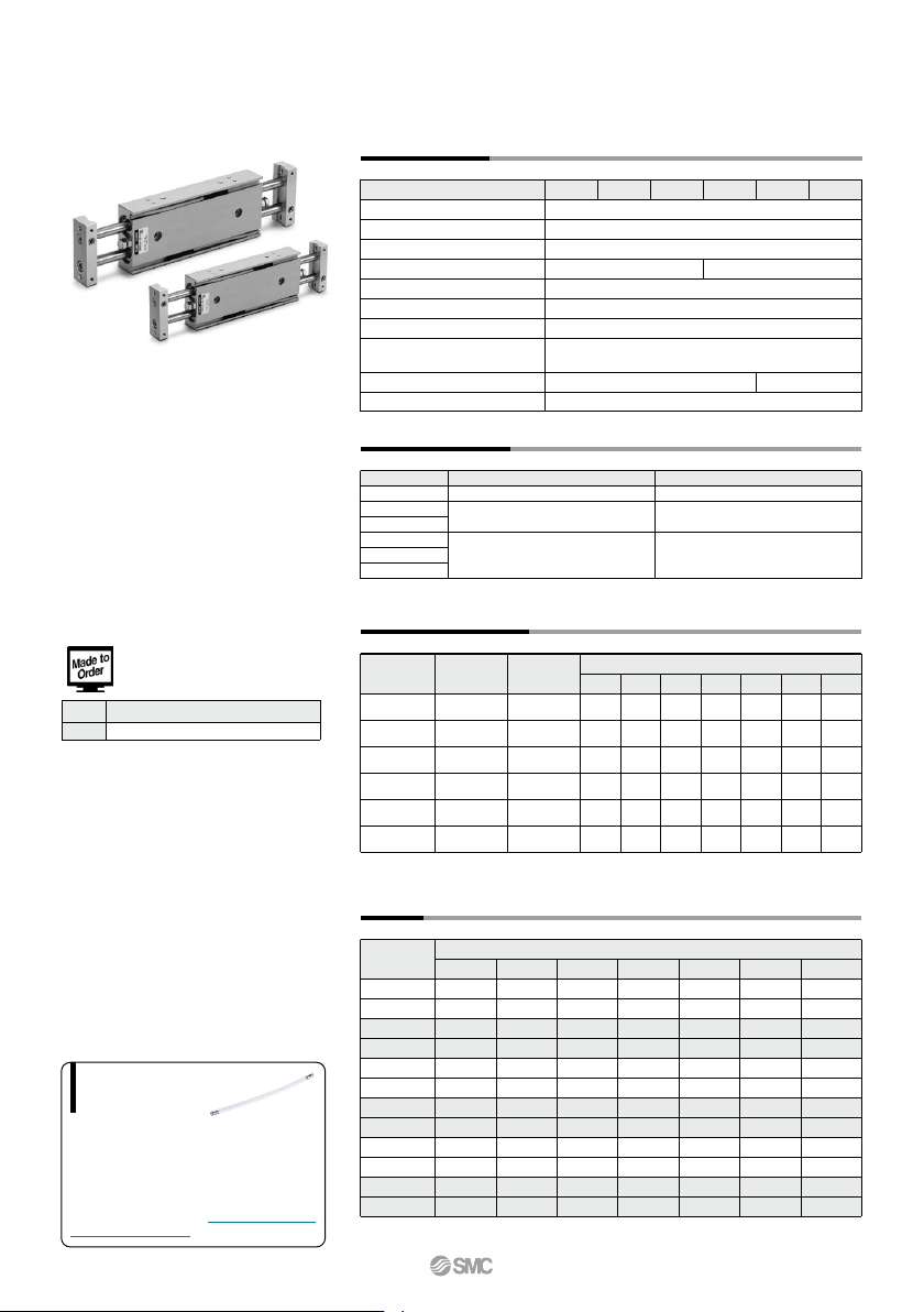
When operating an actuator with a small diameter
and a short stroke at a high frequency, the dew
condensation (water droplet) may occur inside the
piping depending on the conditions.
Simply connecting the moisture control tube to the
actuator will prevent dew condensation from oc-
curring. For details, refer to the IDK series in the
Best Pneumatics No. 6.
Moisture
Control Tube
IDK Series
Specifications
Bore size (mm)
Fluid
Proof pressure
Maximum operating pressure
Minimum operating pressure
Ambient and fluid temperature
Piston speed
Cushion
Stroke adjustable range
Port size
Bearing type
6 10 15
Air (Non-lube)
1.05 MPa
0.7 MPa
–10 to 60°C (No freezing)
50 to 500 mm/s
Bumper is standard on both ends
0 to –10 mm compared to the standard stroke
(Extended end: 5 mm, Retracted end: 5 mm)
Slide bearing, Ball bushing bearing (Same dimensions for both)
0.15 MPa 0.1 MPa
20 25 32
Note) Theoretical output (N) = Pressure (MPa) x Piston area (mm
2
)
∗ For long strokes, it will be made-to-order. (–XB11)
(N)
(kg)
Model
CXSW 6
CXSW10
CXSW15
CXSW20
CXSW25
CXSW32
Rod size
(mm)
4
6
8
10
12
16
4.6
10
25.2
47.1
75.6
121
6.2
20
50.4
94.2
151
241
9.3
30
75.6
141
227
362
12.4
40
101
188
302
482
15.5
50
126
236
378
603
18.6
60
151
283
454
724
21.7
70
176
330
529
844
0.1 0.2 0.3 0.4
Operating pressure (MPa)
0.5 0.6 0.7
Model
10
0.11
0.12
0.24
0.25
0.43
0.47
0.71
0.75
1.06
1.07
2.04
2.06
20
0.13
0.13
0.26
0.27
0.45
0.50
0.74
0.79
1.11
1.12
2.12
2.15
30
0.14
0.15
0.28
0.29
0.48
0.52
0.78
0.82
1.17
1.18
2.21
2.23
40
0.16
0.16
0.30
0.31
0.51
0.55
0.82
0.86
1.22
1.23
2.29
2.32
50
0.17
0.18
0.32
0.33
0.54
0.58
0.85
0.90
1.28
1.29
2.38
2.41
75
—
—
0.37
0.38
0.61
0.65
0.95
0.99
1.41
1.42
2.59
2.62
100
—
—
0.42
0.43
0.68
0.42
1.04
1.08
1.55
1.56
2.81
2.83
Standard stroke (mm)
CXSWM
CXSWL
CXSWM
CXSWL
CXSWM
CXSWL
CXSWM
CXSWL
CXSWM
CXSWL
CXSWM
CXSWL
6
6
10
10
15
15
20
20
25
25
32
32
Piston area
(mm
2
)
31
100
252
471
756
1206
M5 x 0.8 Rc 1/8
Standard Stroke
CXSW 6
CXSW10
CXSW15
CXSW20
CXSW25
CXWS32
Model
(mm)
Theoretical Output
Weight
Standard stroke
10, 20, 30, 40, 50
10, 20, 30, 40, 50, 75, 100
10, 20, 30, 40, 50
Long stroke
—
125, 150, 175, 200
75, 100, 125, 150
–XB11 Long stroke
Symbol Specifications
Made to Order Specifications
Click here for details
CXSW Series
776
A
Maximum Load Mass Deflection at the Plate End
Non-rotating accuracy
Allowable Kinetic Energy
Bore size (mm)
6 to 32
±0.03 mm
CXSWM (Slide bearing)
CXSWL (Ball bushing bearing)
Bore size (mm)
6 to 32
±0.1°
CXSWM (Slide bearing)
CXSWL (Ball bushing bearing)
4
3.5
3
2.5
2
1.5
1
0.5
0
0 20 40 60 80 100
Cylinder stroke (mm)
Maximum load mass W (kg)
ø32
ø25
ø20
CXSWM (Slide bearing)
CXSWL (Ball bushing bearing)
ø15
ø10
ø6
40
20
10
4
2
1
0.5
0.4
0.3
0.2
0.1
0.05
0 50
Cylinder speed Vp (mm/s)
Load mass W (kg)
100 200 300 500 1000
CXSW32
CXSW25
CXSW20
CXSW15
CXSW10
CXSW6
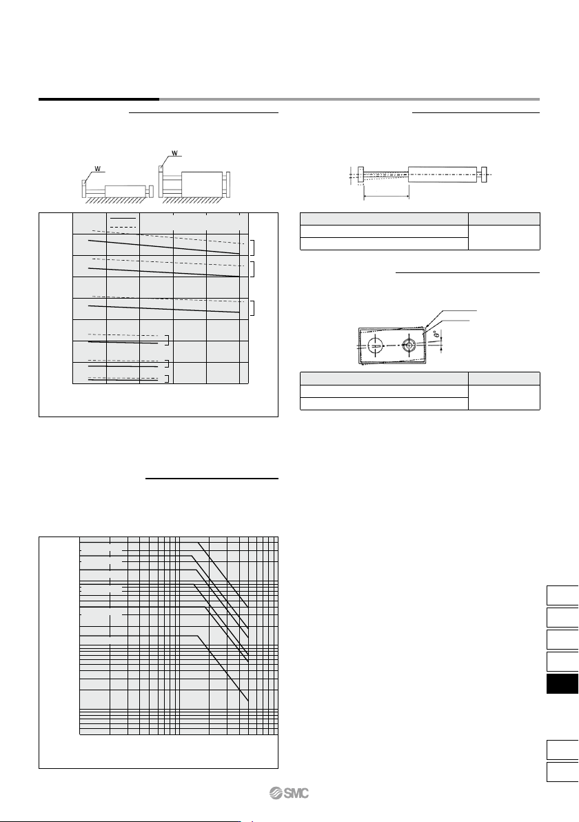
Operating Conditions
When the cylinder is mounted as shown in the diagrams below, the
maximum load mass W should not exceed the values illustrated in the
graph immediately following the diagrams.
Operate a vertically mounted cylinder with a load mass and cylinder
speed not exceeding the ranges shown in the graph below. A horizontally
mounted cylinder should also be operated with a load weight less than the
ranges given in the graph at left. Cylinder speed should be adjusted using
a speed controller.
An approximate plate-end deflection X without a load is shown in the table
below.
Non-rotating accuracy θ° without a load should be less than or equal to
the value provided in the table below as a guide.
Deflection X mm
Extended rod
Housing
Plate
Please consult with SMC regarding the maximum load mass for long
strokes depending on your specific usage conditions.
Note)
CXSW Series
Dual Rod Cylinder
Double Rod Type
777
CX2
CXW
CXT
CXSJ
CXS
D-
-X
CXS
r u i y w !7!8!2 !3@0@3@2@1
q et!1 o !0 !8
r u i y w!3@2@0@3@1 !7!4!5!2
q!8!0!1 ot e
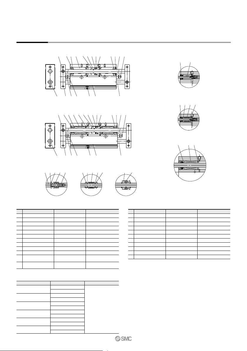
Construction
CXSWM (Slide bearing)
CXSWL (Ball bushing bearing)
CXSW6 CXSW10
CXSWM6
CXSWL6
CXSWL10, 15
CXSW25, 32
(Piston part)
w y @3 i @3 y y i
r !5 !6
!9 r !5 !6
!9 r
@3 y i e
No.
1
2
3
4
5
6
7
8
9
10
Description Material
Aluminum alloy
Carbon steel
Carbon steel
Aluminum bearing alloy
Aluminum alloy
Aluminum alloy
Aluminum alloy
—
Carbon steel
Carbon steel
Note
Hard anodized
Hard chrome plated
Hard chrome plated
Hard anodized
Chromated
Chromated
Nickel plated
Zinc chromated
Housing
Piston rod A
Piston rod B
Rod cover
Plate
Piston A
Piston B
Magnet
Bumper bolt
Hexagon nut
Component Parts
Note) Piston rod for CXSL is quenched.
No.
13
14
15
16
17
18
19
20
21
22
23
Description Material
Special steel
Synthetic resin
—
Synthetic resin
Urethane
Chromium steel
Aluminum alloy
NBR
NBR
NBR
NBR
Note
Phosphate coated
Nickel plated
Retaining ring
Bumper holder
Ball bushing
Bearing spacer
Bumper
Plug
Seal retainer
Piston seal
Rod seal
O-ring
O-ring
Component Parts
Replacement Parts/Seal Kit
Bore size (mm) Kit no. Contents
Set of nos. above
@0, @1 and @2
CXSWM6-PS
CXSWL6-PS
CXSWM10-PS
CXSWL10APS
CXSWM15-PS
CXSWL15APS
CXSWM20-PS
CXSWL20APS
CXSWM25-PS
CXSWL25APS
CXSWM32-PS
CXSWL32APS
6
10
15
20
25
32
Hexagon socket head
cap screw
Hexagon socket head
set screw
Chromium steel
Chromium steel
Zinc chromated
Zinc chromated
11
12
∗ For CXSWL6, aluminum bearing alloy is used for !6.
∗ Seal kit includes @0 to @2. To order them, use the order number given in the left
table.
∗ Since the seal kit does not include a grease pack, order it separately.
Grease pack part no.: GR-S-010 (10 g)
∗
∗
∗
CXSW Series
778