6-2-2-p0723-0782-cxsj_en.pdf - 第58页
r u i y w !7 !8 !2 !3 @0 @3 @2 @1 q e t !1 o !0 !8 r u i y w !3 @2 @0 @3 @1 !7 !4 !5 !2 q !8 !0 !1 o t e Construction CXSWM (Slide bearing) CXSWL (Ball bushing bearing) CXSW 6 CXSW 10 CXSWM6 CXSWL6 CXSWL10, 15 CXSW …
Maximum Load Mass Deflection at the Plate End
Non-rotating accuracy
Allowable Kinetic Energy
Bore size (mm)
6 to 32
±0.03 mm
CXSWM (Slide bearing)
CXSWL (Ball bushing bearing)
Bore size (mm)
6 to 32
±0.1°
CXSWM (Slide bearing)
CXSWL (Ball bushing bearing)
4
3.5
3
2.5
2
1.5
1
0.5
0
0 20 40 60 80 100
Cylinder stroke (mm)
Maximum load mass W (kg)
ø32
ø25
ø20
CXSWM (Slide bearing)
CXSWL (Ball bushing bearing)
ø15
ø10
ø6
40
20
10
4
2
1
0.5
0.4
0.3
0.2
0.1
0.05
0 50
Cylinder speed Vp (mm/s)
Load mass W (kg)
100 200 300 500 1000
CXSW32
CXSW25
CXSW20
CXSW15
CXSW10
CXSW6
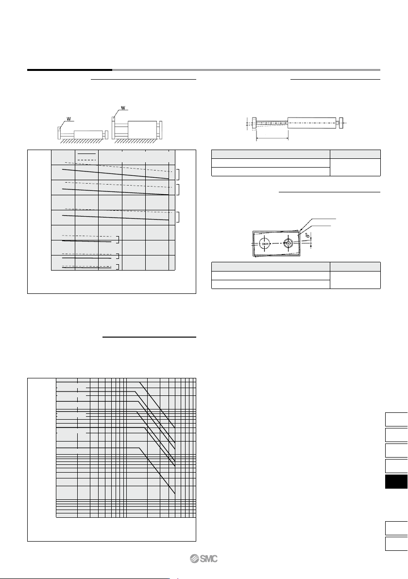
Operating Conditions
When the cylinder is mounted as shown in the diagrams below, the
maximum load mass W should not exceed the values illustrated in the
graph immediately following the diagrams.
Operate a vertically mounted cylinder with a load mass and cylinder
speed not exceeding the ranges shown in the graph below. A horizontally
mounted cylinder should also be operated with a load weight less than the
ranges given in the graph at left. Cylinder speed should be adjusted using
a speed controller.
An approximate plate-end deflection X without a load is shown in the table
below.
Non-rotating accuracy θ° without a load should be less than or equal to
the value provided in the table below as a guide.
Deflection X mm
Extended rod
Housing
Plate
Please consult with SMC regarding the maximum load mass for long
strokes depending on your specific usage conditions.
Note)
CXSW Series
Dual Rod Cylinder
Double Rod Type
777
CX2
CXW
CXT
CXSJ
CXS
D-
-X
CXS
r u i y w !7!8!2 !3@0@3@2@1
q et!1 o !0 !8
r u i y w!3@2@0@3@1 !7!4!5!2
q!8!0!1 ot e
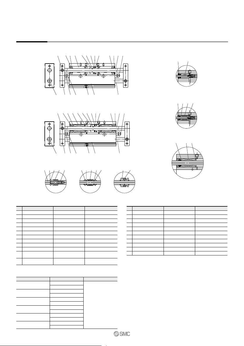
Construction
CXSWM (Slide bearing)
CXSWL (Ball bushing bearing)
CXSW6 CXSW10
CXSWM6
CXSWL6
CXSWL10, 15
CXSW25, 32
(Piston part)
w y @3 i @3 y y i
r !5 !6
!9 r !5 !6
!9 r
@3 y i e
No.
1
2
3
4
5
6
7
8
9
10
Description Material
Aluminum alloy
Carbon steel
Carbon steel
Aluminum bearing alloy
Aluminum alloy
Aluminum alloy
Aluminum alloy
—
Carbon steel
Carbon steel
Note
Hard anodized
Hard chrome plated
Hard chrome plated
Hard anodized
Chromated
Chromated
Nickel plated
Zinc chromated
Housing
Piston rod A
Piston rod B
Rod cover
Plate
Piston A
Piston B
Magnet
Bumper bolt
Hexagon nut
Component Parts
Note) Piston rod for CXSL is quenched.
No.
13
14
15
16
17
18
19
20
21
22
23
Description Material
Special steel
Synthetic resin
—
Synthetic resin
Urethane
Chromium steel
Aluminum alloy
NBR
NBR
NBR
NBR
Note
Phosphate coated
Nickel plated
Retaining ring
Bumper holder
Ball bushing
Bearing spacer
Bumper
Plug
Seal retainer
Piston seal
Rod seal
O-ring
O-ring
Component Parts
Replacement Parts/Seal Kit
Bore size (mm) Kit no. Contents
Set of nos. above
@0, @1 and @2
CXSWM6-PS
CXSWL6-PS
CXSWM10-PS
CXSWL10APS
CXSWM15-PS
CXSWL15APS
CXSWM20-PS
CXSWL20APS
CXSWM25-PS
CXSWL25APS
CXSWM32-PS
CXSWL32APS
6
10
15
20
25
32
Hexagon socket head
cap screw
Hexagon socket head
set screw
Chromium steel
Chromium steel
Zinc chromated
Zinc chromated
11
12
∗ For CXSWL6, aluminum bearing alloy is used for !6.
∗ Seal kit includes @0 to @2. To order them, use the order number given in the left
table.
∗ Since the seal kit does not include a grease pack, order it separately.
Grease pack part no.: GR-S-010 (10 g)
∗
∗
∗
CXSW Series
778
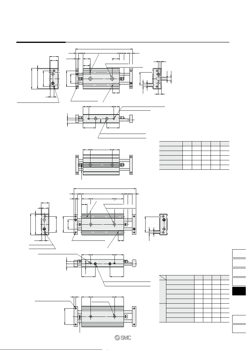
12
∗
12
∗
3
3
6
(13)(Z)
(10)
W
(13)
ZZ
5.5S8
5.6
3.2
6
22.7
8
7
14
16
2.75
5.5
3
1
28
±0.2
±0.2
16
5
6.3
(13)
ø4
10
28
37
35
SS
13
8
2 x ø6.5
counterbore depth
3.3
2 x ø3.2
through
(Opposite side: Same)
2 x R3.5
∗
2 x R3.5
∗
4 x M3 x 0.5
(Through-hole)
2 x 2 x M3 x 0.5 (Through-hole)
2 x 2 x M3 x 0.5 thread depth 4.5
35
20
(20)
8.5
35
7.5
46
44
33.6
6.3
5
7
5
ZZ
8S
ø6
998
4
1
1
15
17
(Z)(20)4
35
20
30
(20)
30
(Z)
2 x R3.5
∗
20 (20)
12
∗
12
∗
2 x R3.5
∗
SS
Z
4 x M3 x 0.5 thread depth 5
thread depth 7
2 x M4 x 0.7
(Through-hole)
(Opposite side: Same)
2 x ø6.5
counterbore depth
3.3
2 x ø3.4
through
2 x 2 x M4 x 0.7
4 x M3 x 0.5 thread depth 5
2 x 2 x M3 x 0.5 thread depth 4.5
±0.2
±0.2
±0.2
(Piping port) (Opposite side: Same)
∗
Equipped with plug at time of shipment
Opposite side not equipped with plug
2 x 2 x M5 x 0.8 thread depth 4.5
22.522.5
(Piping port) (Opposite side: Same)
∗
Equipped with plug at time of shipment
Opposite side not equipped with plug
2 x 2 x M5 x 0.8 thread depth 4.5
Model
CXSW6-10
CXSW6-20
CXSW6-30
CXSW6-40
CXSW6-50
WZZZSSS
10
20
30
40
50
40
50
60
70
80
46
56
66
76
86
103
123
143
163
183
66
76
86
96
106
(mm)
Model
CXSW10-10
CXSW10-20
CXSW10-30
CXSW10-40
CXSW10-50
CXSW10-75
CXSW10-100
CXSW10-125
CXSW10-150
ZZZSSS
10
20
30
40
50
75
100
125
150
52
62
72
82
92
117
142
167
192
136
156
176
196
216
266
316
366
416
92
102
112
122
132
157
182
207
232
(mm)
Dimensions: ø6, ø10
CXSW6
CXSW10
∗ Only the CXSW10-10 and the CXSW10-20 have
a groove cut out for installing auto switches.
(The dimensions are marked “∗”.)
Standard stroke
Long stroke
(–XB11)
∗ Only the CXSW6-10 and the CXSW6-20 have a
groove cut out for installing auto switches.
(The dimensions are marked “∗”.)
CXSW Series
Dual Rod Cylinder
Double Rod Type
779
CX2
CXW
CXT
CXSJ
CXS
D-
-X
CXS
A