00196775-0102_OM_DockingStation_SX_EN.pdf - 第28页
4 Operation Docking Station for SIPLACE SX Changeover Tables 4.1 Controls and Indicators Operating Manual 24 4.1.1 CAN Bus Addresses The CAN bus addresses that can be set are indicated on the sticker located below the sw…
23
Docking Station for SIPLACE SX Changeover Tables 4 Operation
Operating Manual 4.1 Controls and Indicators
4 Operation
4.1 Controls and Indicators
1
2
3
4
5
7
6
1
2
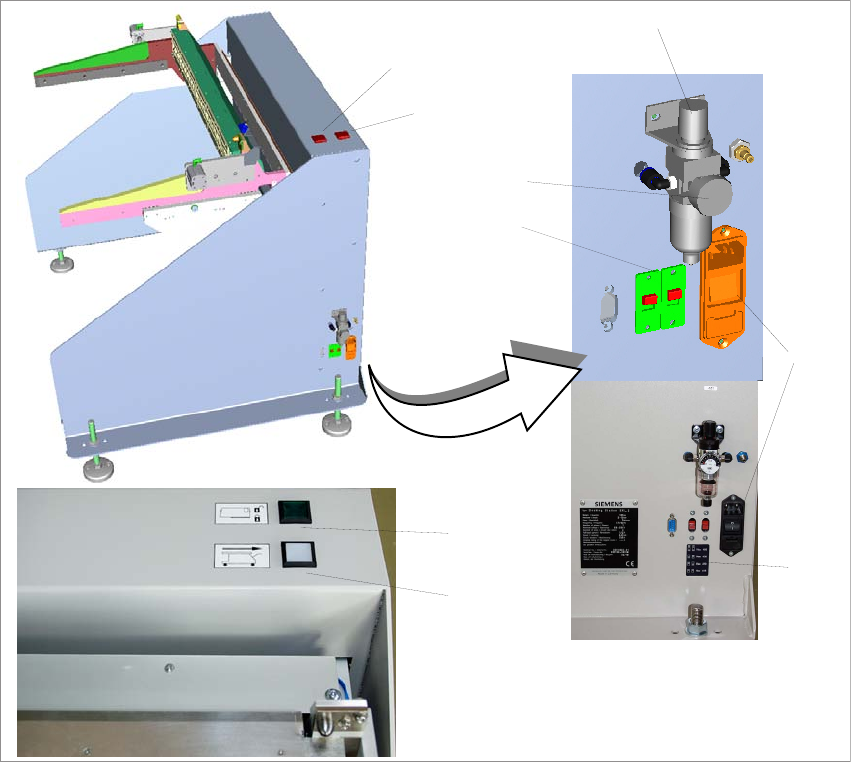
Fig. 4 - 1 Docking station SIPLACE SX – controls and indicators
(1) Changeover table release (white button)
(2) Feeder locking and release (green button)
(3) Knob for setting the operating pressure
(4) Pressure gauge for indicating the operating pressure
(5) Switches S1 and S2 for setting the CAN bus address
(6) Sticker explaining the switches S1 and S2 for CAN bus addressing
(7) Power switch
4 Operation Docking Station for SIPLACE SX Changeover Tables
4.1 Controls and Indicators Operating Manual
24
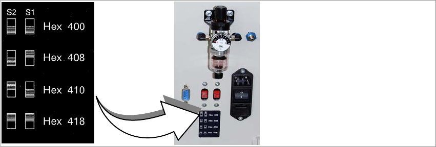
4.1.1 CAN Bus Addresses
The CAN bus addresses that can be set are indicated on the sticker located below the switches
S1 and S2.
Fig. 4 - 2 CAN bus addresses
25
Docking Station for SIPLACE SX Changeover Tables 4 Operation
Operating Manual 4.2 Adjusting the Conveyor Height
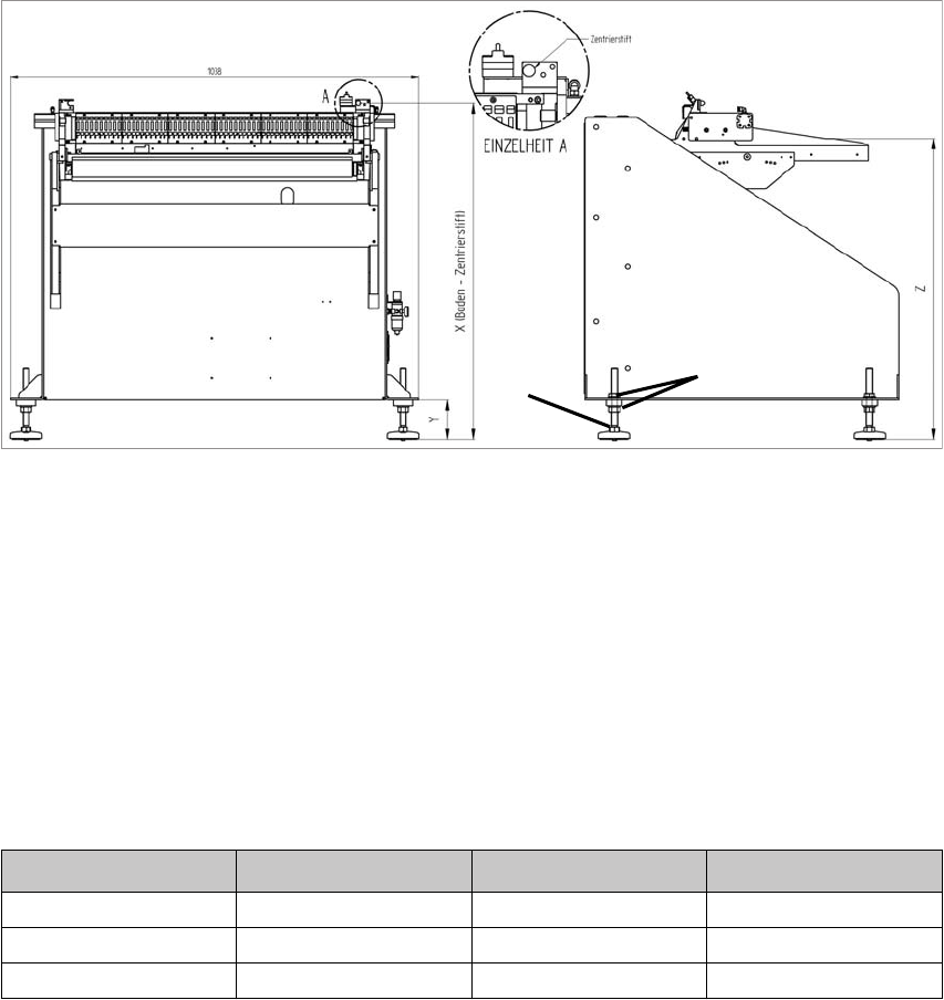
4.2 Adjusting the Conveyor Height
Flat spanners of size SW 22 and SW 24 and a spirit level are required.
2
1
Fig. 4 - 3 Adjusting the conveyor height
(1) 2x lock nut SW 24
(2) 1x adjusting screw SW 22
To adjust the conveyor height, proceed as follows:
1. Loosen the lock nuts on all adjusting feet.
2. Use the adjusting screws to adjust the dimension Y (see table).
3. Check that the machine is horizontal (ûsing the spirit level).
Machine height Dimension X Dimension Y Dimension Z
900 mm 859 mm 100 mm 770 mm
930 mm 889 mm 130 mm 800 mm
950 mm 909 mm 150 mm 820 mm