N7201A652E.pdf - 第106页
NPM- TT2 EJM1EE-MB-02 O-04 2-2-2 -15 Engineer mode 6 Compo- nent names Menu configur a tion 8 Operating procedure 2-2-2 Parameter Machine menu Checks picku p position offset. Feeder Checks the offsets of squeegee-axis an…
NPM-TT2 EJM1EE-MB-02O-04
2-2-2-14
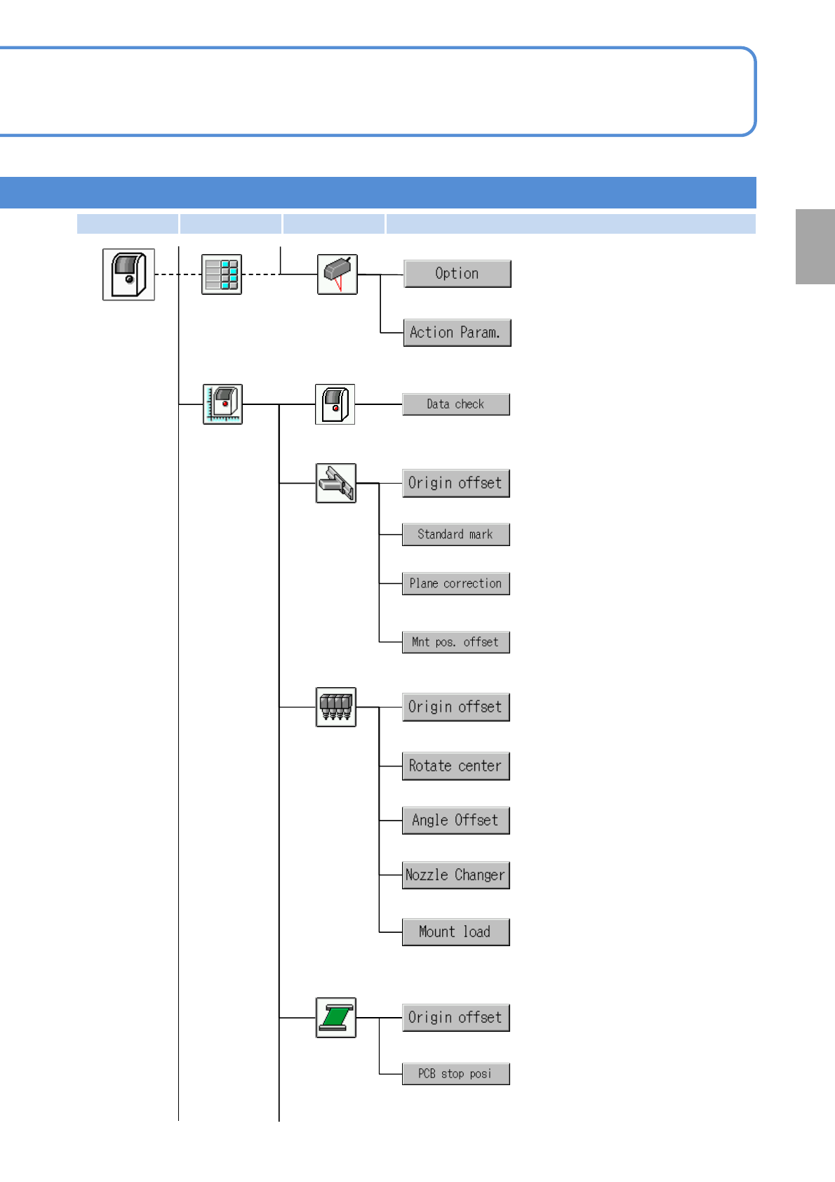
Confirms data check results.
Whole
Parameter
Checks the origin offset.
Checks the offset of XY-reference mark.
Checks the parameter for the plane
correction of the placement range.
Checks the offset of placement position.
XY unit
Checks the head rotation center offset.
Checks the offset at each head angle.
Checks the offset of the head origin.
Checks the nozzle changer offset.
Head
Checks the parameter for load control.
Checks the origin offset.
Conveyor
Checks PCB control position offset.
(displayed when the 3-nozzle head is installed)
Preparation
Machine
menu
Setup
Configures option functions.
Height
sensor
Configures the parameters.
First layer Second layer Third layer Fourth layer
NPM-TT2 EJM1EE-MB-02O-04
2-2-2-15
Engineer mode 6
Compo-
nent
names
Menu configuration 8
Operating procedure
2-2-2
Parameter
Machine
menu
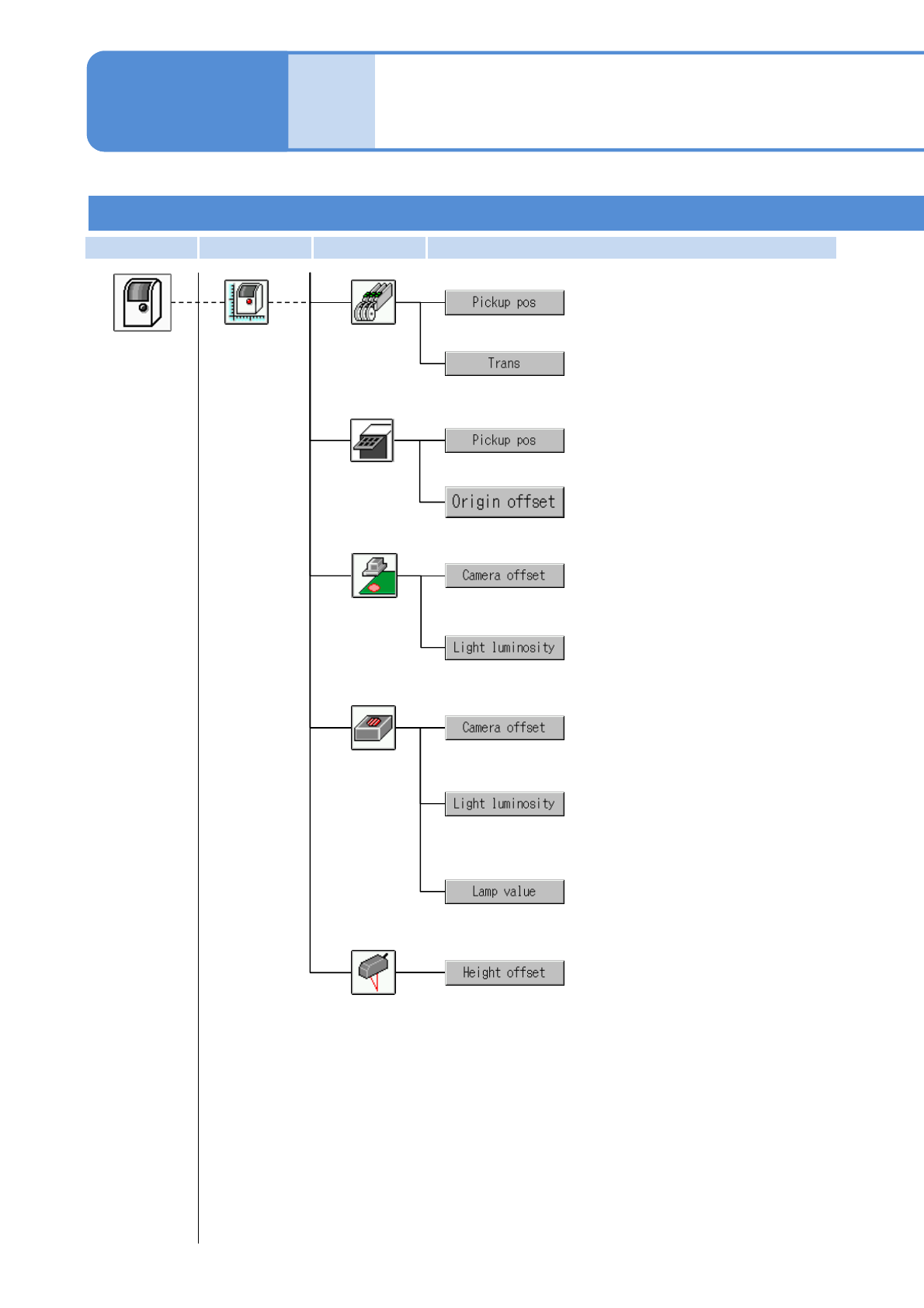
Checks pickup position offset.
Feeder
Checks the offsets of squeegee-axis
and transcription position.
Tray
Checks the origin offset.
Checks pickup position offset.
Checks the offset and scale of the
head camera.
Checks the lamp values to be set to
the recognition device.
Head
camera
Checks the offset and magnification
of the component recognition camera.
Checks the lamp values to be set to
the recognition device.
Checks and enters the lamp values to
be set to the recognition device.
First layer Second layer Third layer Fourth layer
Multi-
recognition
camera
Checks and enters the offset
correction coefficient of the height
sensor.
Height sensor
NPM-TT2 EJM1EE-MB-02O-04
2-2-2-16
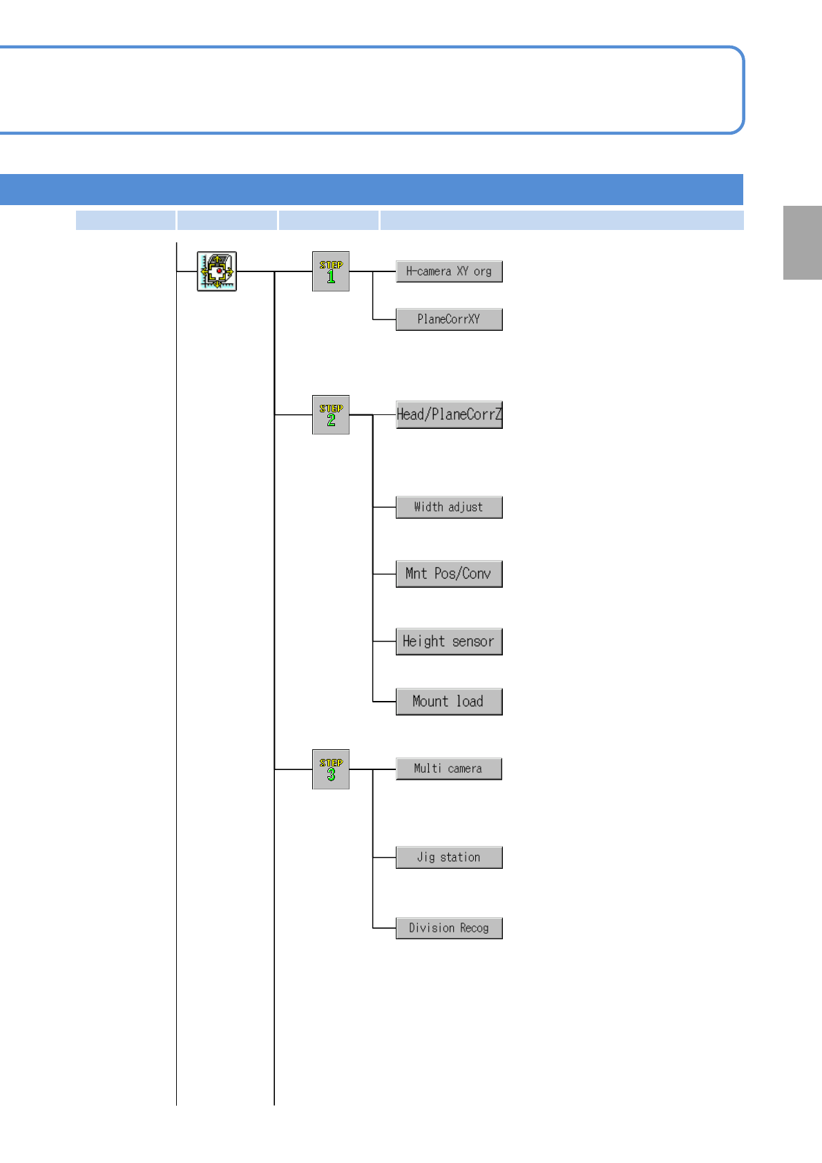
Measures XY-origin and the head
camera.
Obtains measurements required to
calculate the XY offset of the
placement range.
Calibration
First step
Measures the origin offset of Z-axis,
and obtains measurements required
to calculate the height offset of the
placement range.
Configures the origin offset of the
adjustment width.
Second step
Configures the parameter for load
control.
Sets a PCB stop position and
placement height offset.
Measures scan position offset, line
camera magnification and camera tilt.
Third step
(for the 3-nozzle head)
Corrects the height sensor.
Preparation
First layer Second layer Third layer Fourth layer
Sets the origin offset of the head θ-
axis and the multi- recognition
camera magnification.
Measures the offset value related to
split recognition.
(displayed when split recognition is set)