N7201A652E.pdf - 第153页
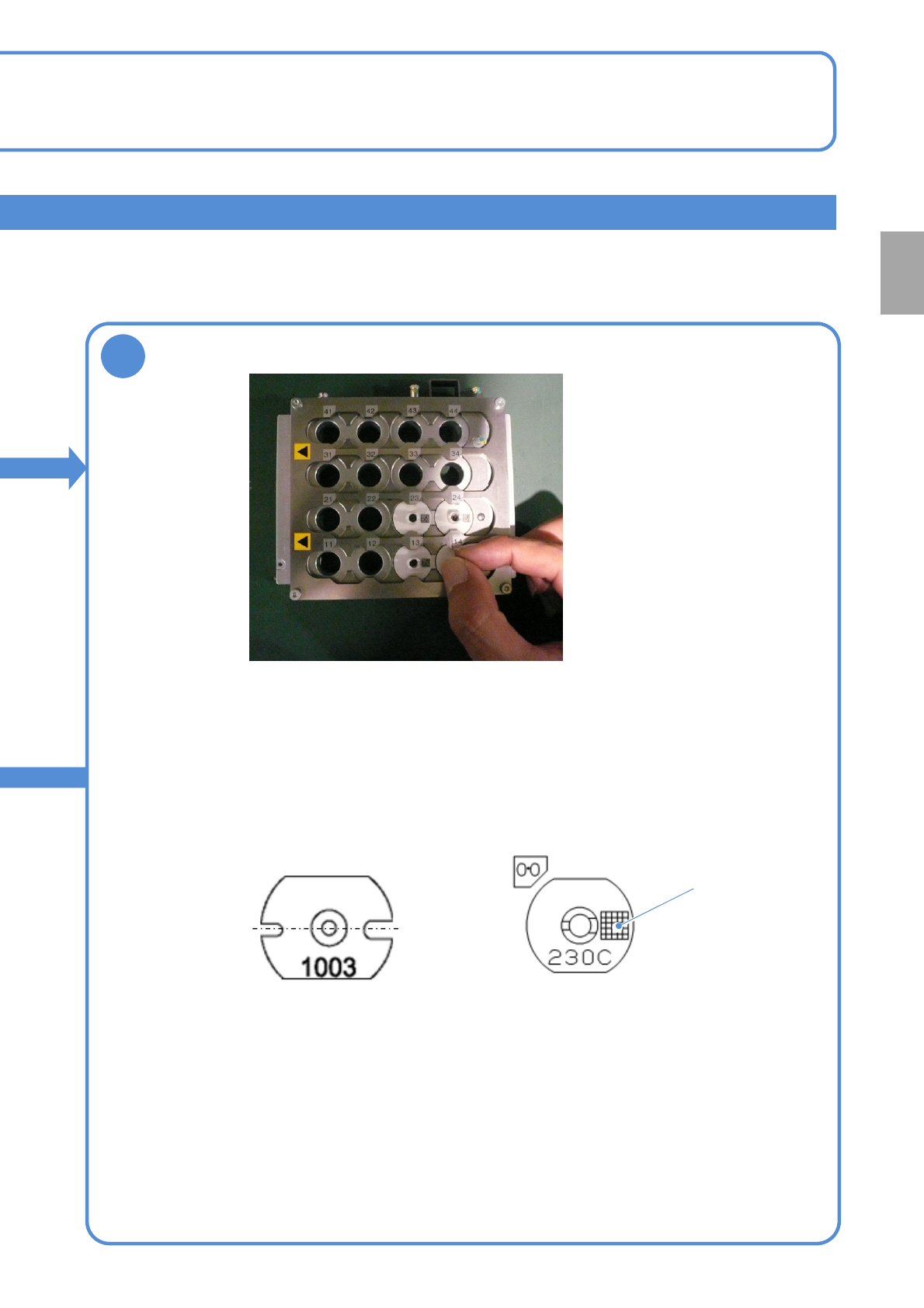
NPM- TT2 EJM1EE-MB -02O-04 2 ● As far as the nozzles for the 3- nozzle head use are concerned , be careful of the right and left grooves orientation . Narrow groove Wide groove Feeder table side 2-5-2 -4 ● Place the 8-/1…
NPM-TT2 EJM1EE-MB-02O-04
Individu-
al
prepara-
tion
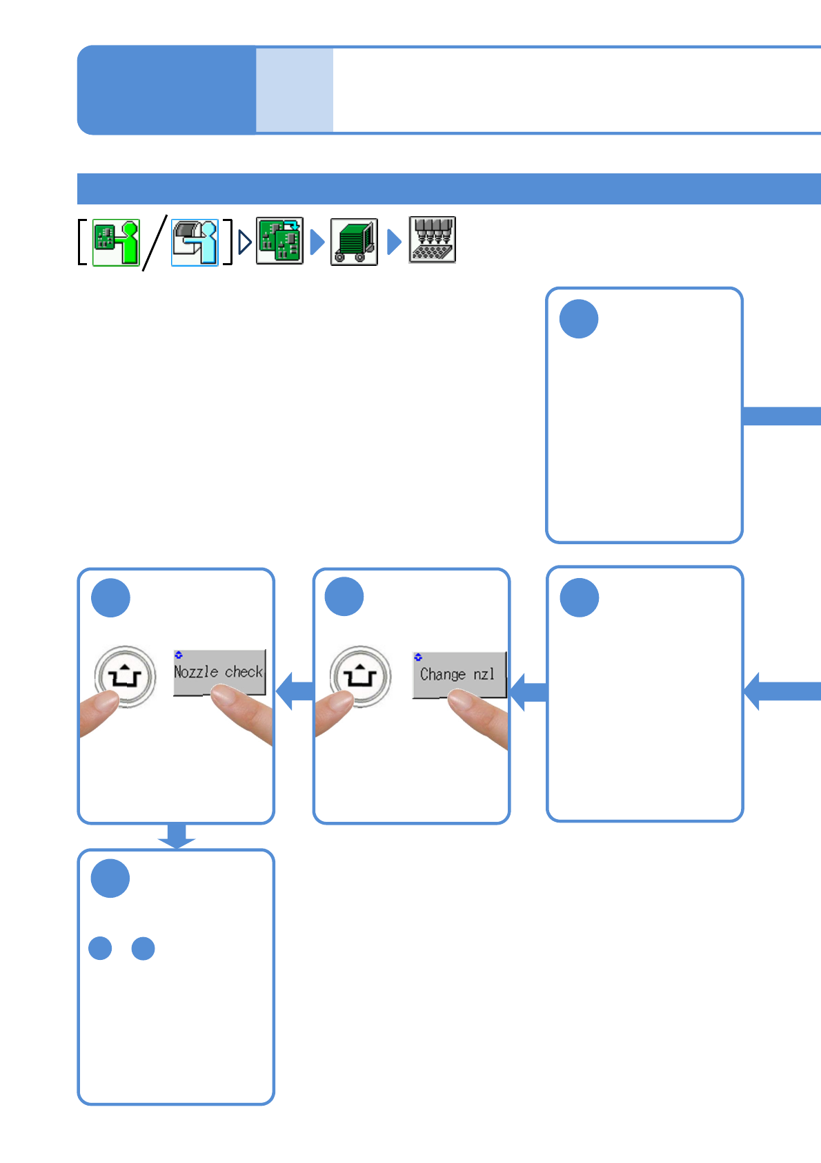
Replacing the nozzle 2
Replacing nozzles
1
2-5-2-3
4
(Based on the data, nozzles
in the nozzle changer are
attached to the head)
5
●If the attached nozzles are
improper, the warning
message appears.
Change them out for
correct ones.
6
Repeat the steps from
to and replace
desired nozzles
1
5
Remove the
nozzle changer
3
Attach the
nozzle changer
(→P.2-5-1)
(→P.2-5-1)
Operating procedure
2-5-2
NPM-TT2 EJM1EE-MB-02O-04
2
●As far as the nozzles for the 3-
nozzle head use are concerned, be
careful of the right and left grooves
orientation.
Narrow
groove
Wide
groove
Feeder table side
2-5-2-4
●Place the 8-/12-/16-nozzle head use nozzles, on which 2D
code is marked, in the direction as shown in the following
figures.
●Option settings can detect nozzle types by 2D code and thus
help prevent the nozzles from being placed in the wrong places.
(for information on how to set, see P.5-1-1)
Feeder table side
<Nozzle for 8-nozzle head><Nozzle for 3-nozzle head>
2D code
Replace nozzles
Preparation
NPM-TT2 EJM1EE-MB-02O-04
Individu-
al
prepara-
tion
Replacing the nozzle 3
2-5-2-5
Operating procedure
2-5-2
1
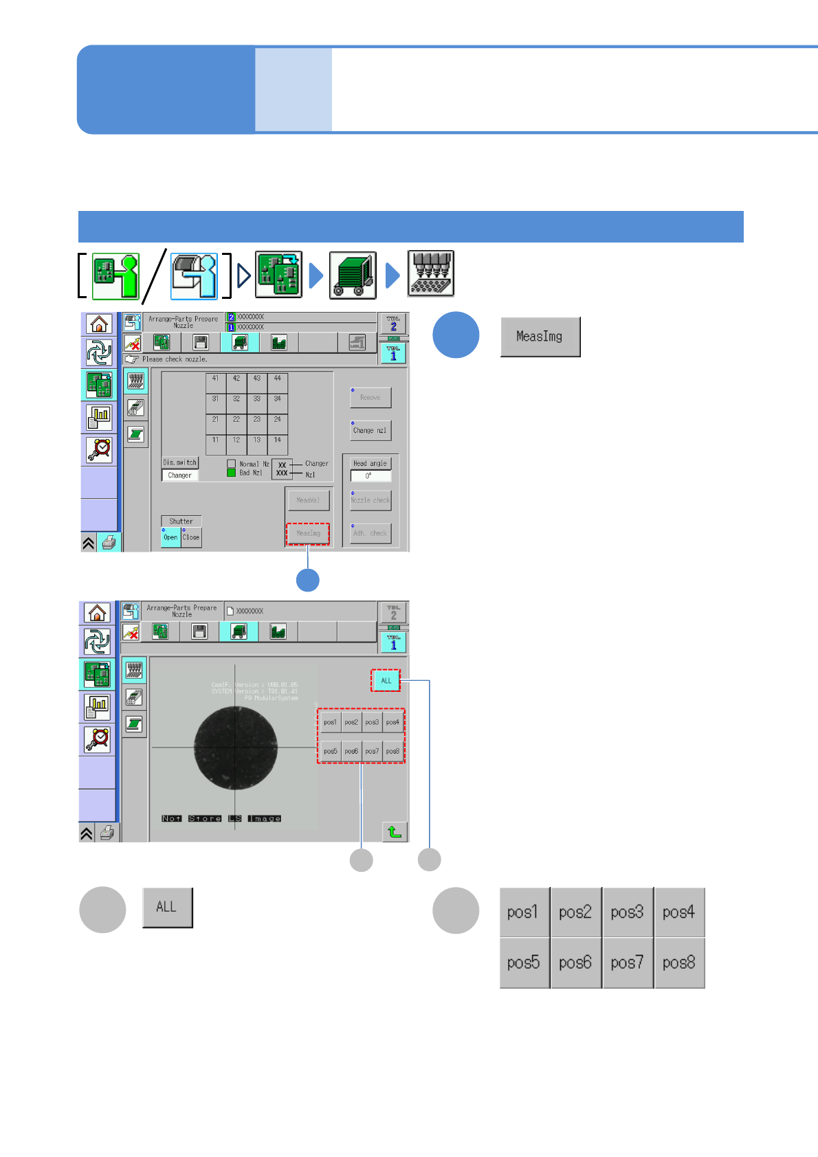
B
A
1
This is used to display the recognition image captured during a nozzle check.
You need to carry out a [Nozzle check] to display the measurement screen.
The screens for 8-nozzle heads are used here as an example to illustrate; however, the same procedure is
also applicable to 3-nozzle heads.
Nozzle setting (measurement image) screen
Displays the image of the overall head.
The enlarged image at each nozzle position
is displayed.
<MeasImg> screen:
Displays the recognition image that was
displayed when the nozzle setting was
checked on the <Attachment> screen.
B
A