N7201A652E.pdf - 第159页
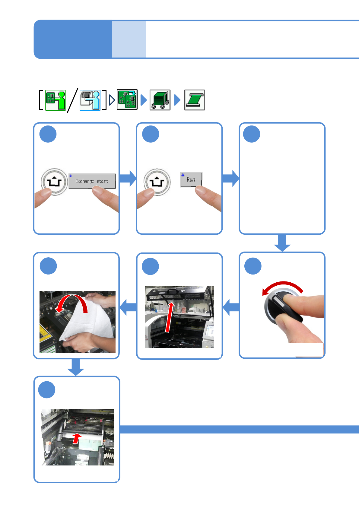
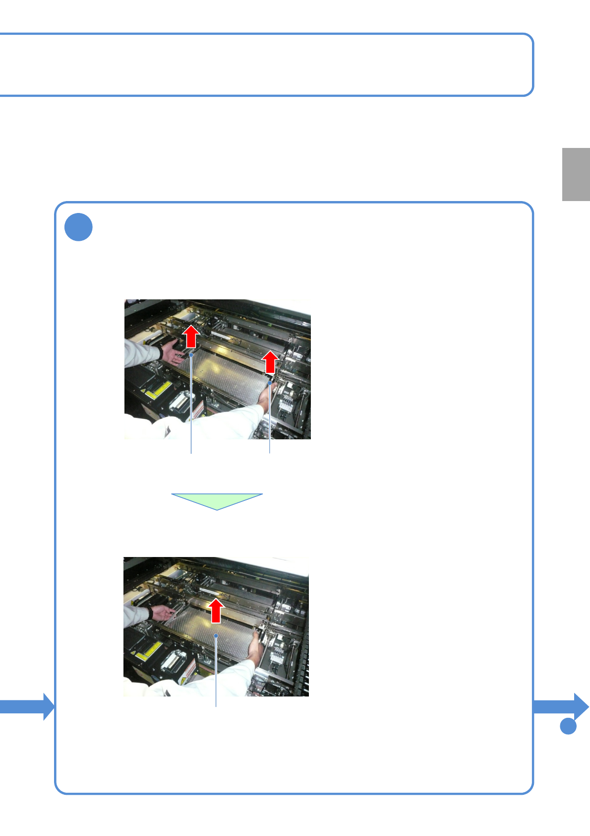
NPM- TT2 EJM1EE-MB -02O-04 2-5-3 -2 8 Remove the PCB support blocks Removal lever ● Draw out the PCB suppor t block. ● Draw it out slowly with both han ds. ● Be carefu l not to drop a foreign body on the line camera (LED…
NPM-TT2 EJM1EE-MB-02O-04
ACTIVATION
ACTIVATION
2-5-3-1
1
After removing
PCBs
2 3
Cover the line
camera with the
lint-free cloth
Individu-
al
prepara-
tion
Operating procedure
2-5-3
●The PCB support block
raises
Detach the tray
feeder or the feeder
cart
●For a tray feeder
(→[Maintenance] P.14-8)
●For a feeder cart
(→[Maintenance] P.3-2)
OFF
SERVO
5
4
7
6
●Only for the exchange cart
Hold the feeder
table cover to
the back
●Only for the exchange cart
●Only for the exchange cart
Setting support pins 1
NPM-TT2 EJM1EE-MB-02O-04
2-5-3-2
8
Remove the PCB support blocks
Removal lever
●Draw out the PCB support block.
●Draw it out slowly with both hands.
●Be careful not to drop a foreign body on
the line camera (LED lighting) or bump it.
●Remove both lane as the same way.
PCB support block
●Lift up the right and left levers in the front.
Removal lever
To
9
Preparation

NPM-TT2 EJM1EE-MB-02O-04
ACTIVATION
ACTIVATION
2-5-3-3
9
Insert support pins to the PCB support block
●Install the support pins as entire PCB is evenly supported.
●Be careful not to bump pins against the components on the
reverse side of PCB.
●Using the support pin set jig (option) can prevent support pins
from inserting in wrong positions.
(Jig: N610131762AD)
Individu-
al
prepara-
tion
Operating procedure
2-5-3
14
SERVO
ON
15
16
17
●The PCB support block
lowers
Attach the tray
feeder or the feeder
cart
●For a tray feeder
(→[Maintenance] P.14-8)
●For a feeder cart
(→[Maintenance] P.3-2)
●Only for the exchange cart
Setting support pins 2