N7201A652E.pdf - 第160页
NPM- TT2 EJM1EE-MB-02 O-04 ACTIVATION ACTIVATION 2-5-3 -3 9 Insert support pins to the PCB support block ● Install the support pins as entire PCB is evenly supported. ● Be careful not to bump pins against the components …
NPM-TT2 EJM1EE-MB-02O-04
2-5-3-2
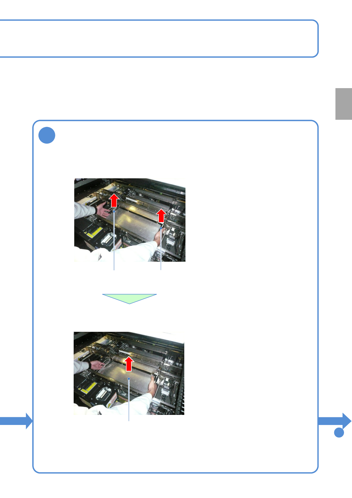
8
Remove the PCB support blocks
Removal lever
●Draw out the PCB support block.
●Draw it out slowly with both hands.
●Be careful not to drop a foreign body on
the line camera (LED lighting) or bump it.
●Remove both lane as the same way.
PCB support block
●Lift up the right and left levers in the front.
Removal lever
To
9
Preparation

NPM-TT2 EJM1EE-MB-02O-04
ACTIVATION
ACTIVATION
2-5-3-3
9
Insert support pins to the PCB support block
●Install the support pins as entire PCB is evenly supported.
●Be careful not to bump pins against the components on the
reverse side of PCB.
●Using the support pin set jig (option) can prevent support pins
from inserting in wrong positions.
(Jig: N610131762AD)
Individu-
al
prepara-
tion
Operating procedure
2-5-3
14
SERVO
ON
15
16
17
●The PCB support block
lowers
Attach the tray
feeder or the feeder
cart
●For a tray feeder
(→[Maintenance] P.14-8)
●For a feeder cart
(→[Maintenance] P.3-2)
●Only for the exchange cart
Setting support pins 2
NPM-TT2 EJM1EE-MB-02O-04
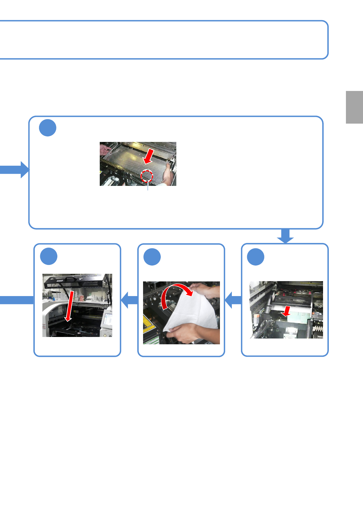
2-5-3-4
10
Attach the PCB support block as there is no tilt (Avoid interfering with the
rail)
●Adjust the guide pins on the main unit to
the holes on the PCB support block.
Guide pin
Remove the
cloth
12 11
13
Put the feeder
table cover back
in its place
●Only for the exchange cart ●Only for the exchange cart
Preparation