N7201A652E.pdf - 第173页
NPM- TT2 EJM1EE-MB-02 O-04 2-5-7 -4 10 Attach the PCB support block (for automatic change) as there is no tilt (A void interfering with the rail) Remove the cloth ● Place the PCB support block while paying attention not …
NPM-TT2 EJM1EE-MB-02O-04
2-5-7-3
Individu-
al
prepara-
tion
Installing support pins (for
automatic change) 2
Operating procedure
2-5-7
9
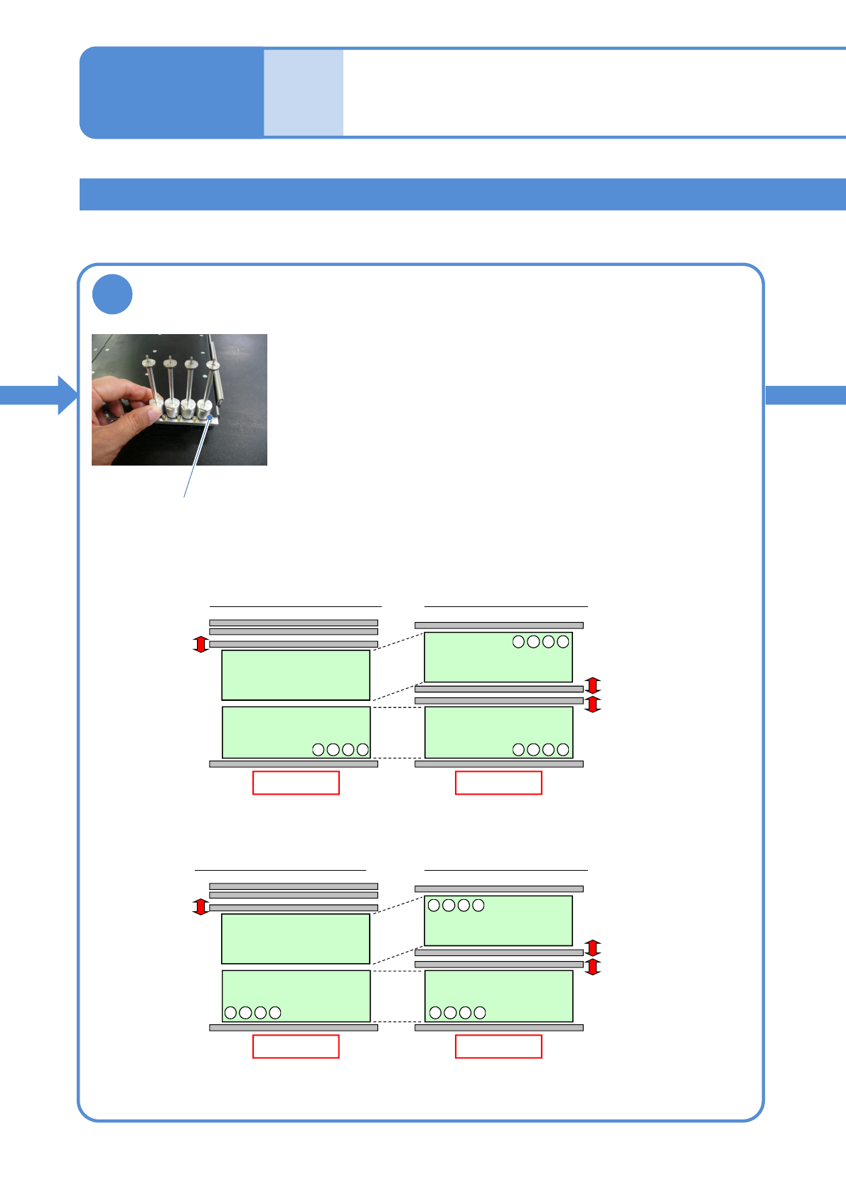
Set the support pins (for automatic change) to
the PCB support block (for automatic change)
●When the support pins are set, be sure to set to the home
position. (Avoid interfering with the conveyor)
● Place support pins with pushing Bolts on the hole position.
(They may interfere with vacuumed support pins during
arrangement of the pins)
●If a PCB flow is from right to left, place pins from the left end in
order. If it is reverse flow, place pins from the right end.
●For single lane mode, set pins only on the fixed rail side.
From left to right
Rear
Front
Arrangement on single lane mode
Front
Lane 2
Lane 1
Arrangement on dual lane mode
Front
4321
・・・
4321
・・・
4321
・・・
From right to left
Rear
Front
Arrangement on single lane mode
Front
Lane 2
Lane 1
Arrangement on dual lane mode
Front
4321
・・・
1234
・・・
1234
・・・
Installing the support pin (for automatic change) 2
Bolt
NPM-TT2 EJM1EE-MB-02O-04
2-5-7-4
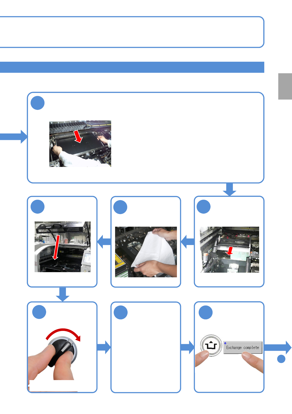
10
Attach the PCB support block (for automatic change) as there is no tilt
(Avoid interfering with the rail)
Remove the
cloth
●Place the PCB support block while paying attention
not to hit the support pins to the rail.
●After it is placed, push the support pins to the bolt,
and make sure that pins are pressed against the bolt.
11
12
13
Attach the tray
feeder or the feeder
cart
●For a tray feeder
(→[Maintenance] P.14-8)
●For a feeder cart
(→[Maintenance] P.3-2)
15 16
14
SERVO
ON
To
17
Put the feeder
table cover back
in its place
●Only for the exchange cart ●Only for the exchange cart
●Only for the exchange cart
Preparation
ACTIVATION
NPM-TT2 EJM1EE-MB-02O-04
Installing support pins
(for automatic change) 3
Operating procedure
2-5-7
2-5-7-5
Individu-
al
prepara-
tion
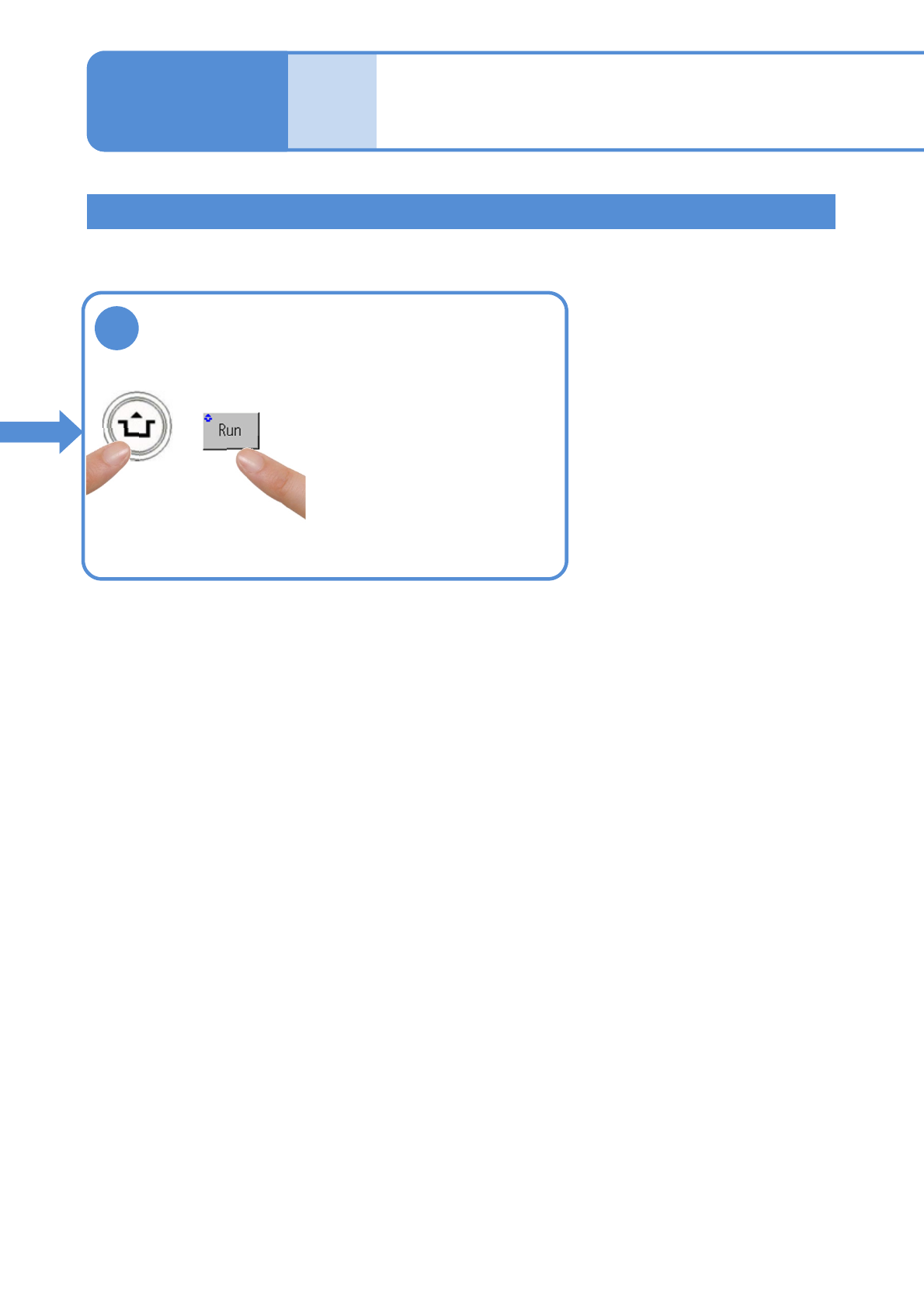
Installing the support pin (for automatic change) 3
●Then, check the number of
support pins actually arranged
on the home position and the
number of support pins being
kept.
17
●The PCB support block
lowers.
ACTIVATION