N7201A652E.pdf - 第194页
NPM- TT2 EJM1EE-MB-03 O-02 Produc- tion informa- tion Ho w to c hec k the scr een in pr oduction w hen stationar y 1 How to check the screen in production 1 ● Displays production information and ope ration status durin g…
NPM-TT2 EJM1EE-MB-03O-02
3-1-4
Production
Produc-
tion
Placement mode
Operating procedure
3-1-4
Feature
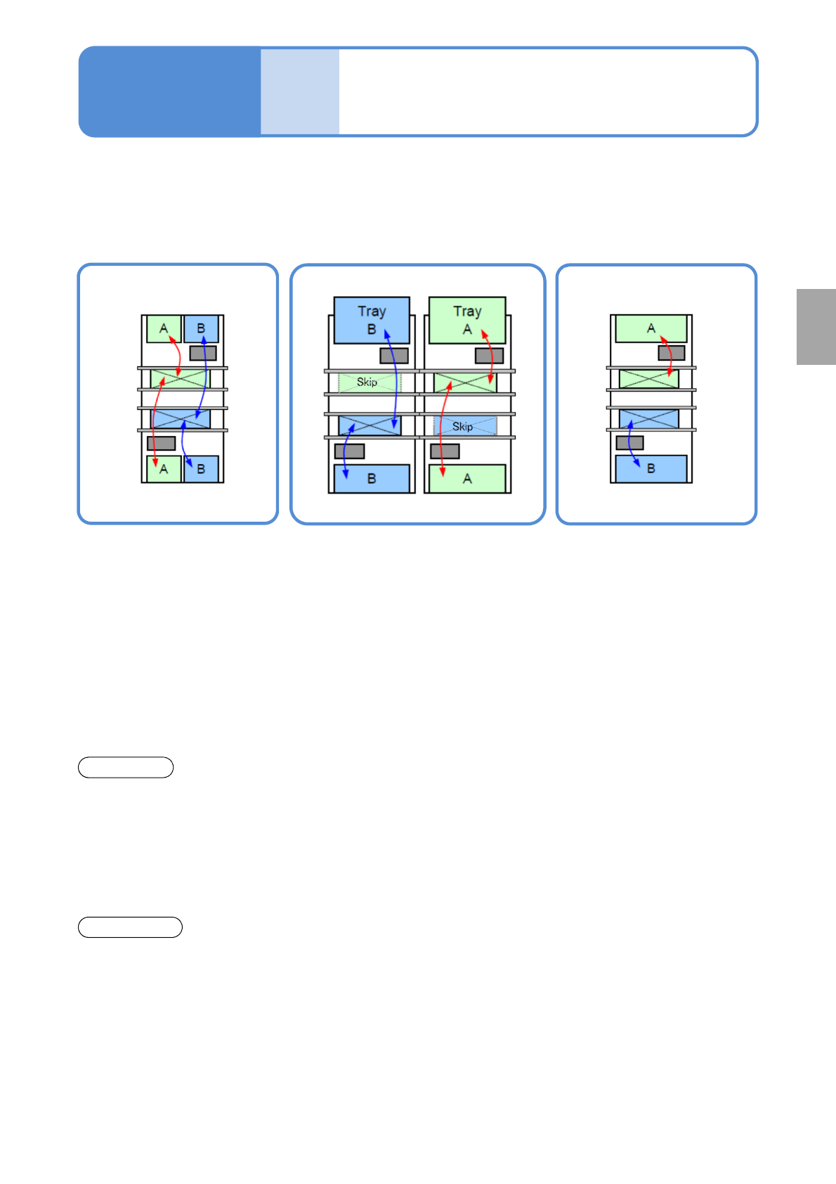
■Alternate mode
●The head moves
alternatively and performs
production.
●Each head produces PCB
on the front and rear lane.
●The head moves
alternatively and after
production of the target
lane completes, it
produces PCB on the other
lane.
■Alternate front (rear) mode ■Independent mode
●Using the front and rear heads,
only PCBs on the front (rear) lane
are produced, and PCBs on the
rear (front) lane are passed through.
●Each head independently
carries out production for
PCBs on each head.
Front head: Front lane
production
Rear head: Rear lane
production
●It minimizes the PCB
transfer loss.
●Production start and stop are
applicable per lane.
●Production start and stop
is applicable per lane.
●It improves productivity
because the head does not
need to wait for head
alternative motion (waiting
for motion of the other
head.
Changeover
●You need to stop the
machine to carry out
changeover for each lane.
●Changeover (changing the
production data or the feeder cart,
or replacing the tray magazine) is
applicable for the suspended lane
while PCBs are passed through.
●Changeover (changing the
production data or
replacing the feeder cart
or the tray magazine) is
applicable for the
suspended lane during
one-side production.
*1)Head standby may arise depending on the PCB size.
*1)
If machine specification is dual lane mode, you can select from the following modes for production.
NPM-TT2 EJM1EE-MB-03O-02
Produc-
tion
informa-
tion
How to check the screen in
production when stationary
1
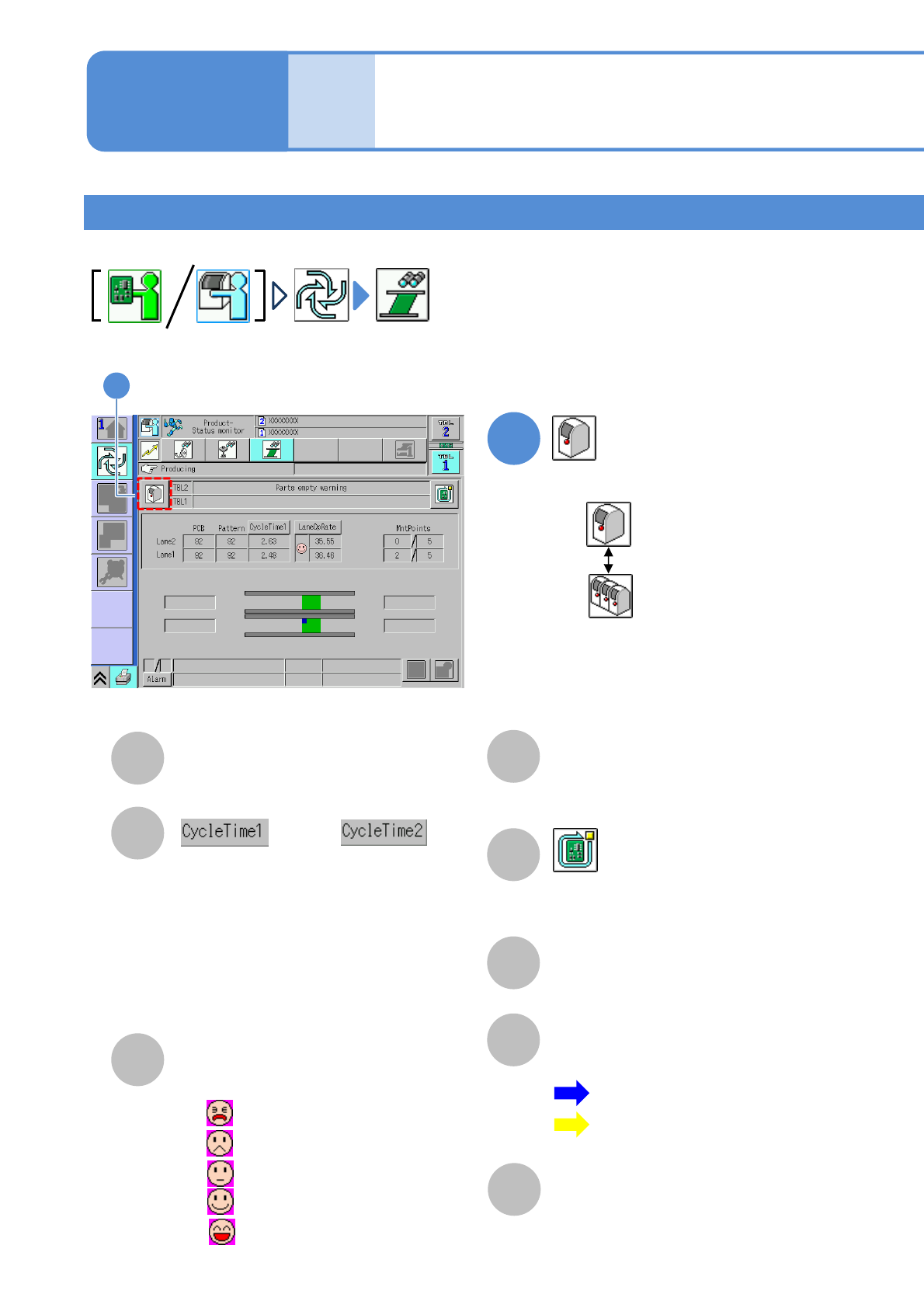
How to check the screen in production 1
●Displays production information and operation status during production.
Operating procedure
3-2-1
3-2-1-1
A
E
B
C
D
F
PCB
The number of produced PCBs/patterns.
Switches the display of time required to
produce a PCB. (Display changes every
time you pressed)
●Cycle time 1
Time from when clamping is completed
before placement until clamping is
released after placement.
●Cycle time 2
Placement time including transfer time.
Rate
Operating rate of the machine.
(Changeable by action parameter)
MntPoints
The number of components that
have been placed/total placement
points.
Stop production after the produced
current PCB. (→P.3-1-2)
Component empty / Component
empty warning
Component empty occurrence condition.
G
Transfer Status
The transfer status and current
position of PCBs are displayed.
H
Warning
Errors and warnings on the
machine are displayed.
or
:Blue…Action status
:Yellow…Standby
Waiting for loading
Waiting for unloading
: 0% to 20% or less
: 20% to 40% or less
: 40% to 60% or less
: 60% to 80% or less
: 80% up to 100%
●
●
●
●
●
1
Choose either by machine or by line
: By machine
: By line
1
■Placement head (alternate mode)
NPM-TT2 EJM1EE-MB-03O-02
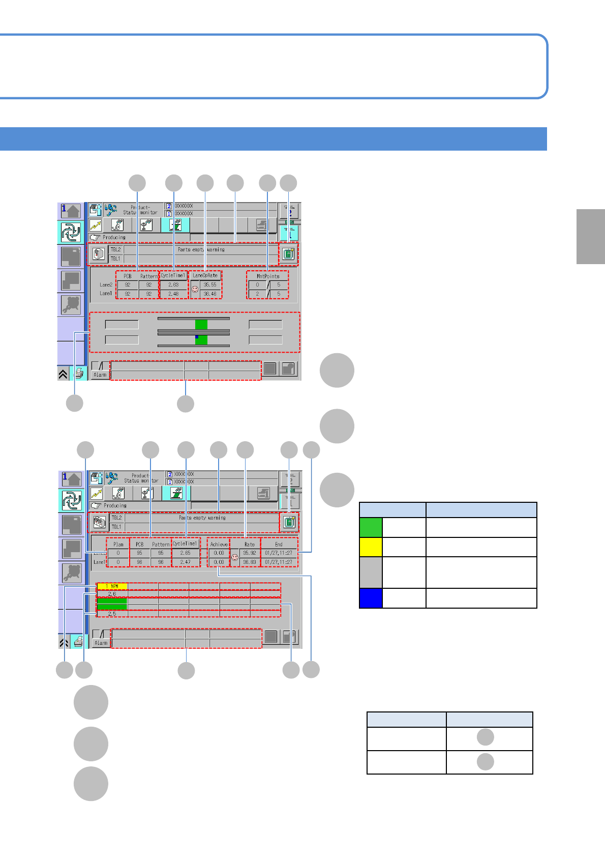
3-2-1-2
Production
G
D EFA B C
H
L
I EFA B C
H
J
K
I
J
K
L
A bottleneck machine position can be
displayed in yellow color in the following
position by LNB setting
.
LNB setting
Display area
By machine
By lane
M N
M
N
L
M
■By machine
■By line
Number of planned PCBs
Estimated end time
Achievement rate
Actual performance in line / Planned PCBs in line
Machine No.(name) to be
connected
Cycle time
Production status
Display color Production status
Green In production
Yellow Under suspended
Gray
Waiting for component
supply
Blue Waiting for processing
■Display position of bottleneck machine
About the setting of LNB, see the [LNB]
operating instructions.
Upper level: Lane 2
Lower level: Lane 1
Upper level: Lane 2
Lower level: Lane 1