N7201A652E.pdf - 第307页
NPM- TT2 EJM1EE-MB -04O-03 4-2-3 -2 Setting change Entering the PCB warpage measurement points data Starting teaching Choosing the measurement points data Adjusting the position Measurement test Saving the data Completio…
NPM-TT2 EJM1EE-MB-04O-03
Pattern 1 Pattern 2
Pattern 3 Pattern 4
4-2-3-1
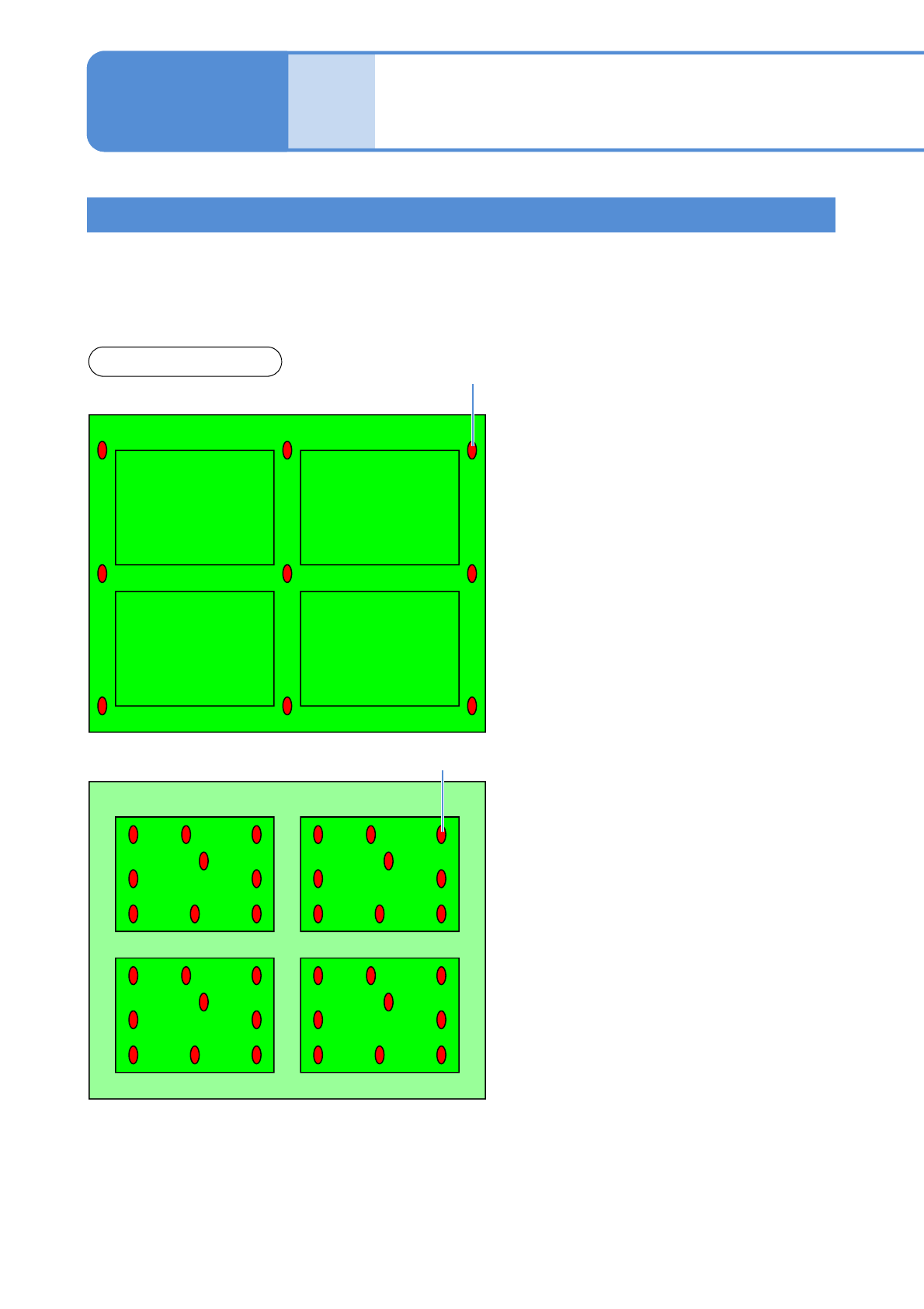
Conceptual drawing
■Warpage mode: PCB
PCB warpage measurement point
■Warpage mode: Pattern
Pattern 1
Pattern 2
Pattern 3 Pattern 4
PCB warpage measurement point
PCB warpage measurement points
Produc-
tion data
teaching
PCB warpage measurement
point teach
(option) 1
Operating procedure
4-2-3
The PCB warpage detection function is available to control the height by predicting PCB warpage. This
function measures the height of a few points on the PCB surface by the height sensor, draws the
approximate curve to be assumed by the measurement result and controls the mount height according to
the approximate curve. PCB warpage measurement and correction mode has two patterns; PCB and
Pattern. You must choose which mode is used depending on PCB warpage condition.
●It is necessary to confirm whether to be appropriate or not the measurement points (surface material, area, the
number of points, arrangement) in advance. (→P.6-1-8)
●The changing PCB data is sent from CPM-DGS in advance. (→P.2-3-3)
●PCB warpage measurement point teach can be performed by the PCB data of the PCB warpage target. [PCB
warpage detection] of the soft switch must be turned ON and the PCB warpage measurement point coordinates
must be registered. (→NPM-DGS 4.3.3 Option setting)
●Before performing measurement point teach, [Measurement by the height sensor] and [PCB warpage
Correction] of the option setting must be turned ON. (→P.5-1-1 Option setting)
NPM-TT2 EJM1EE-MB-04O-03
4-2-3-2
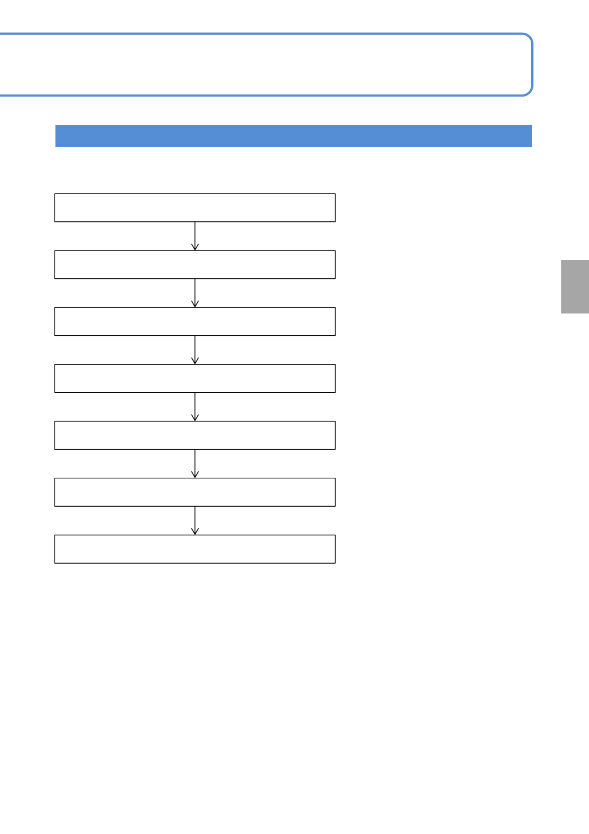
Setting
change
Entering the PCB warpage measurement points data
Starting teaching
Choosing the measurement points data
Adjusting the position
Measurement test
Saving the data
Completion of teaching
Created by NPM-DGS
Teaching Flow
NPM-TT2 EJM1EE-MB-04O-03
4-2-3-3
Produc-
tion data
teaching
PCB warpage measurement
point teach
(option) 2
Operating procedure
4-2-3
2
+
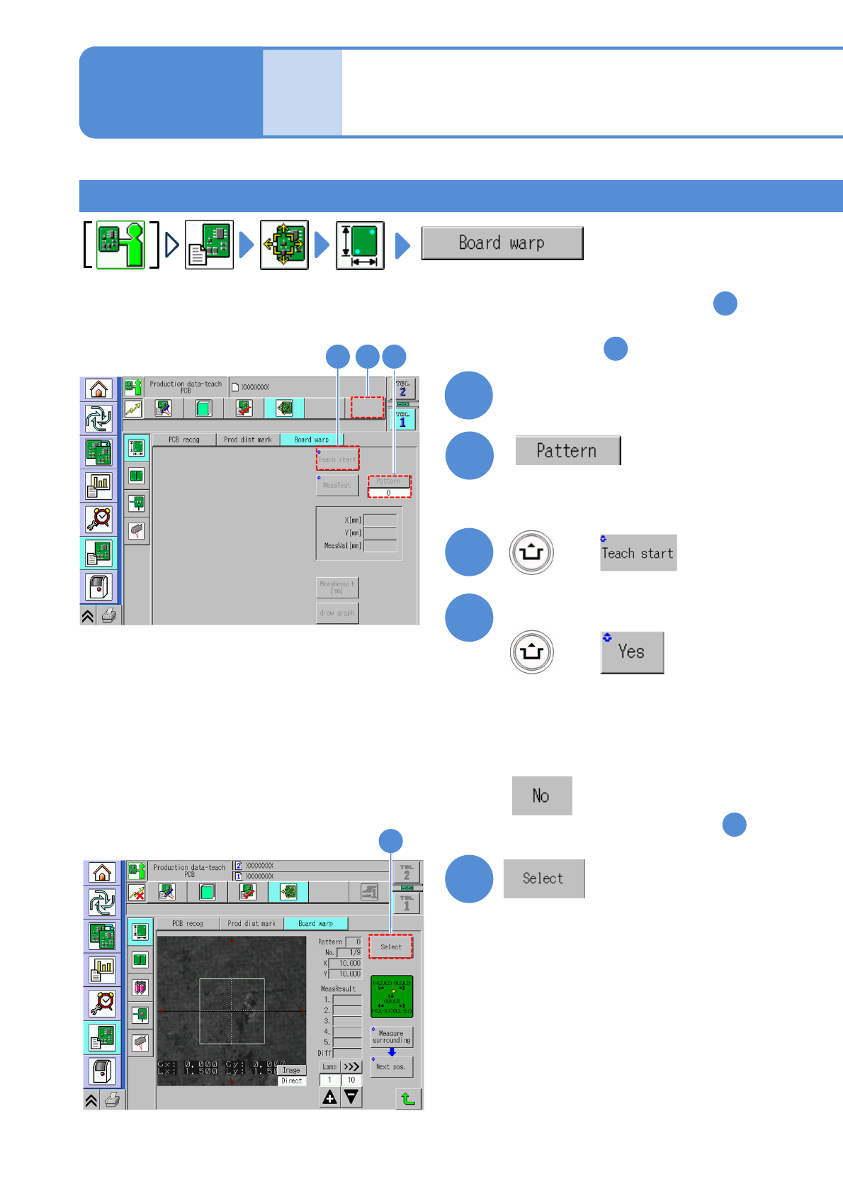
Confirm the message
3
1
(Selectable only when the warpage
mode is pattern.)
●Set the pattern number
4
(Confirm the PCB loading message
and place the PCB.)
5
(The PCB warpage measurement
point data is displayed.)
+
■If you do not operate
Select a lane
(The screen remain as it is in )
1
(The PCB is loaded and the
recognition mark is recognized.)
(For dual lane)
Teaching procedure 1
23
5
1
■For measuring per a point and change
the measurement point: To step
3
■For measuring all points and check
the result: To step
11