N7201A652E.pdf - 第354页
NPM- TT2 EJM1EE-MB-04 O-03 T eaching by specifying component position 2 Produc- tion data teaching Placement coor dina tes teac h 10 Operating procedure 4-2-9 4-2-9 -18 + 14 13 15 15 17 ■ When an image is recognizable 18…
NPM-TT2 EJM1EE-MB-04O-03
Setting
change
4-2-9-17
6
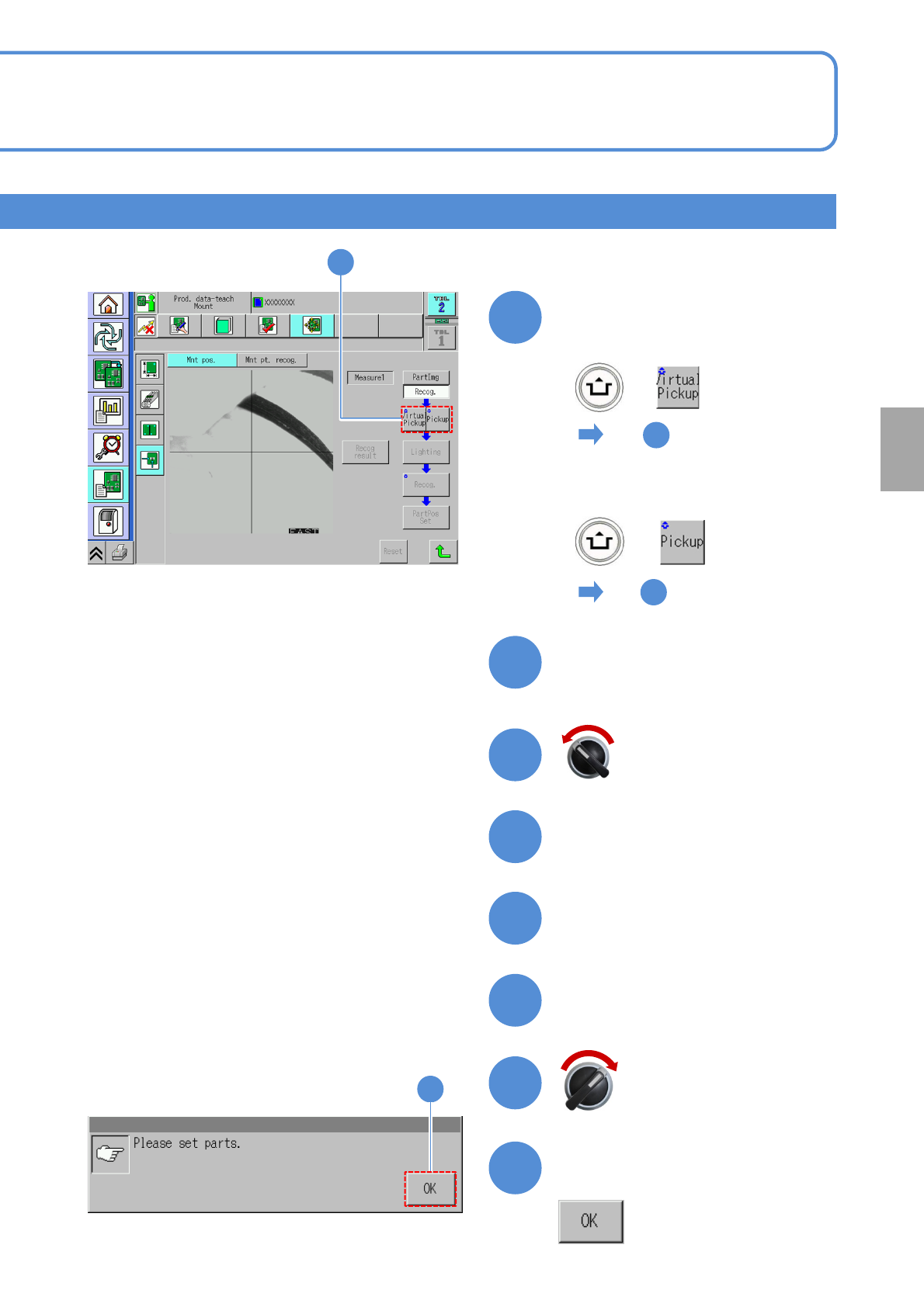
■When a component is picked
up to the nozzle manually
7
To
+
■When a component is picked
up to the nozzle automatically
14
To
+
7
Prepare for component
installation
8
9
10
11
12
Open the safety cover
Servo switch OFF
Install components
Close the safety cover
13
Confirm the message
13
6
Servo switch ON
NPM-TT2 EJM1EE-MB-04O-03
Teaching by specifying component position 2
Produc-
tion data
teaching
Placement coordinates
teach 10
Operating procedure
4-2-9
4-2-9-18
+
14
13
15
15
17
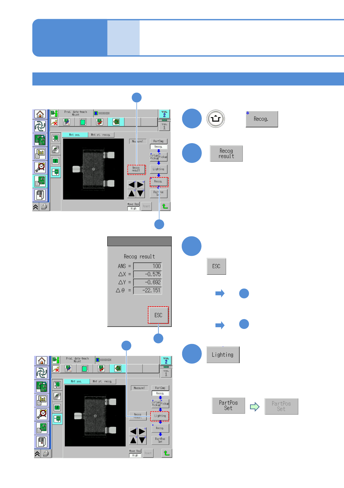
■When an image is recognizable
18
To
■In the case of recognition
error, or unclear image
17
To
17
16
Confirm the recognition result
16
■For recognition error, the button
is grayed out
and becomes disabled
■Adjustment is necessary
since pins for insertion
components are not easy to
recognize
(→P.4-2-1 ‘How to adjust the lamp value’)
NPM-TT2 EJM1EE-MB-04O-03
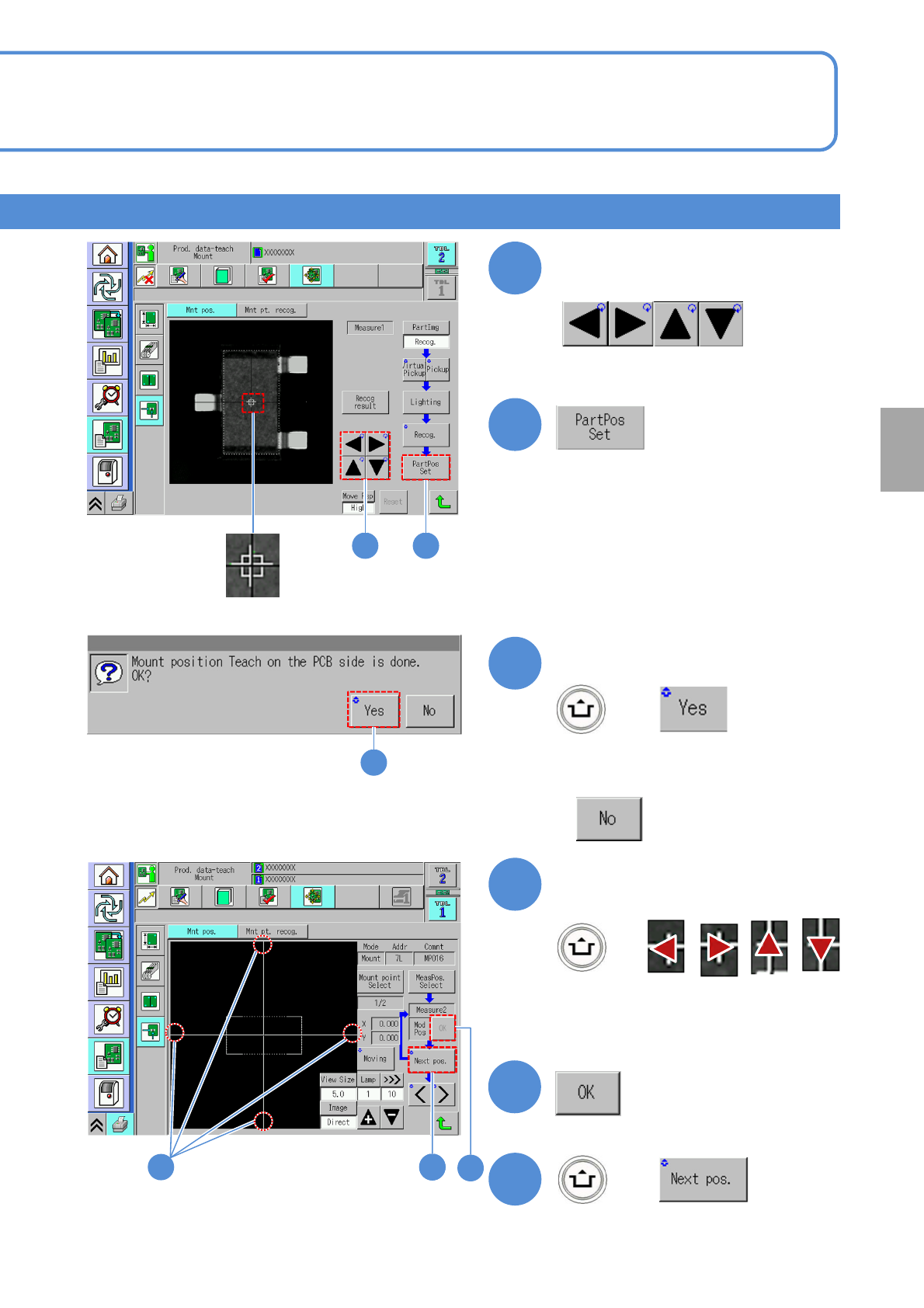
■When you do not perform mount
position teach
Setting
change
4-2-9-19
18
Point a cursor to the electrode
of or a pin of a component
Cursor
18 19
19
Confirm the message
20
21
+
Align the cross line center
21
●Align the cross line center to an
electrode or a hole.
+
23
21
+
20
23
22
22