N7201A652E.pdf - 第409页
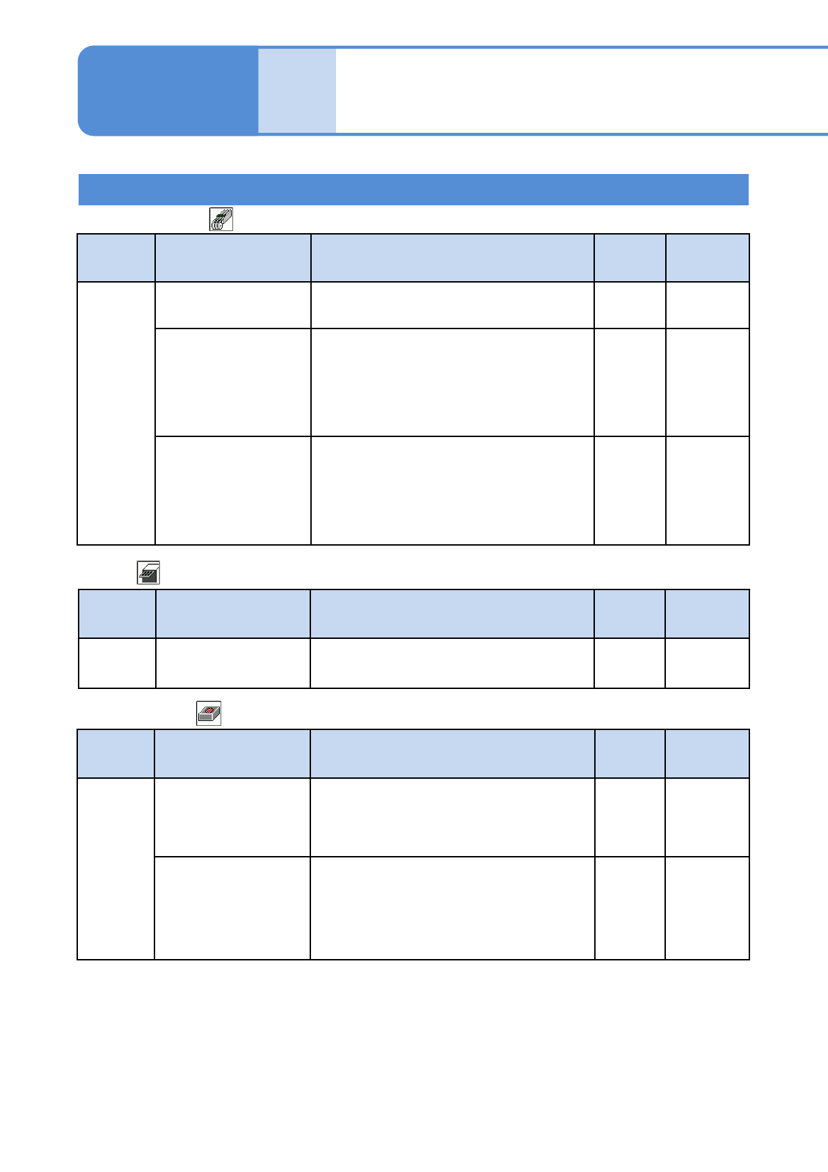
NPM- TT2 EJM1E E-MB-05O-05 5-1-2 -14 System administration Setting information 13 ■ Height sensor Type Item Description Initial value Setting range Determine PCB warpage grade tolerance [%] When PCB warpage is measured, …
NPM-TT2 EJM1EE-MB-05O-05
Unit
setting
Action parameter
setting 7
5-1-2-13
Setting information 12
Operating procedure
5-1-2
■Line camera
Type Item Description Initial
value
Setting
range
Determine
Recog. OK rate [%]
This is a criterion used to judge recognition
results good or bad.
If “ANS” of recognition results falls short of it,
a recognition error occurs.
85 0 to 100
Bad mark judge rate
[%]
This is the threshold for bad mark
recognition block matching.
The block is judged to be OK if the result of
matching is equal to or greater than the
value set here.
85 0 to 100
Type Item Description Initial
value
Setting
range
Mechanic
Tray pickup place gap
[mm]
This gap is added in pickup from trays. 0.5 -2.0 to 2.0
■Tray
■ Transfer (2/2)
Type Item Description Initial
value
Setting
range
Timer
Time Keep thick film
time [s]
Coating thickness formation holding time
for the transcription unit.
30 0 to 600
Stamp material
Spill Detect Invalid
Time (F) [s]
After transcription materials at the front side
are automatically supplied, spill detection is
disabled during the set time period.
●It assumes the time between the start of
material dripping off and until dripping off
stops.
0.5 0.0 to 5.0
Stamp material
SpillDetect Invalid
Time (R) [s]
After transcription materials at the rear side
are automatically supplied, spill detection is
disabled during the set time period.
●It assumes the time between the start of
material dripping off and until dripping off
stops.
0.5 0 .0 to 5.0

NPM-TT2 EJM1EE-MB-05O-05
5-1-2-14
System
administration
Setting information 13
■Height sensor
Type Item Description Initial
value
Setting
range
Determine
PCB warpage grade
tolerance [%]
When PCB warpage is measured, if the
tolerance obtained form the height
measurement value exceeds the set value,
the single stop error occurs.
0.5 0.0 to 10.0
Local height result
tolerance [mm]
When the local height on the several
locations are measured, if the minimum and
maximum values exceed the set value, the
single stop error occurs.
0.5 0.1 to 2.0
NPM-TT2 EJM1EE-MB-05O-05
Unit
setting
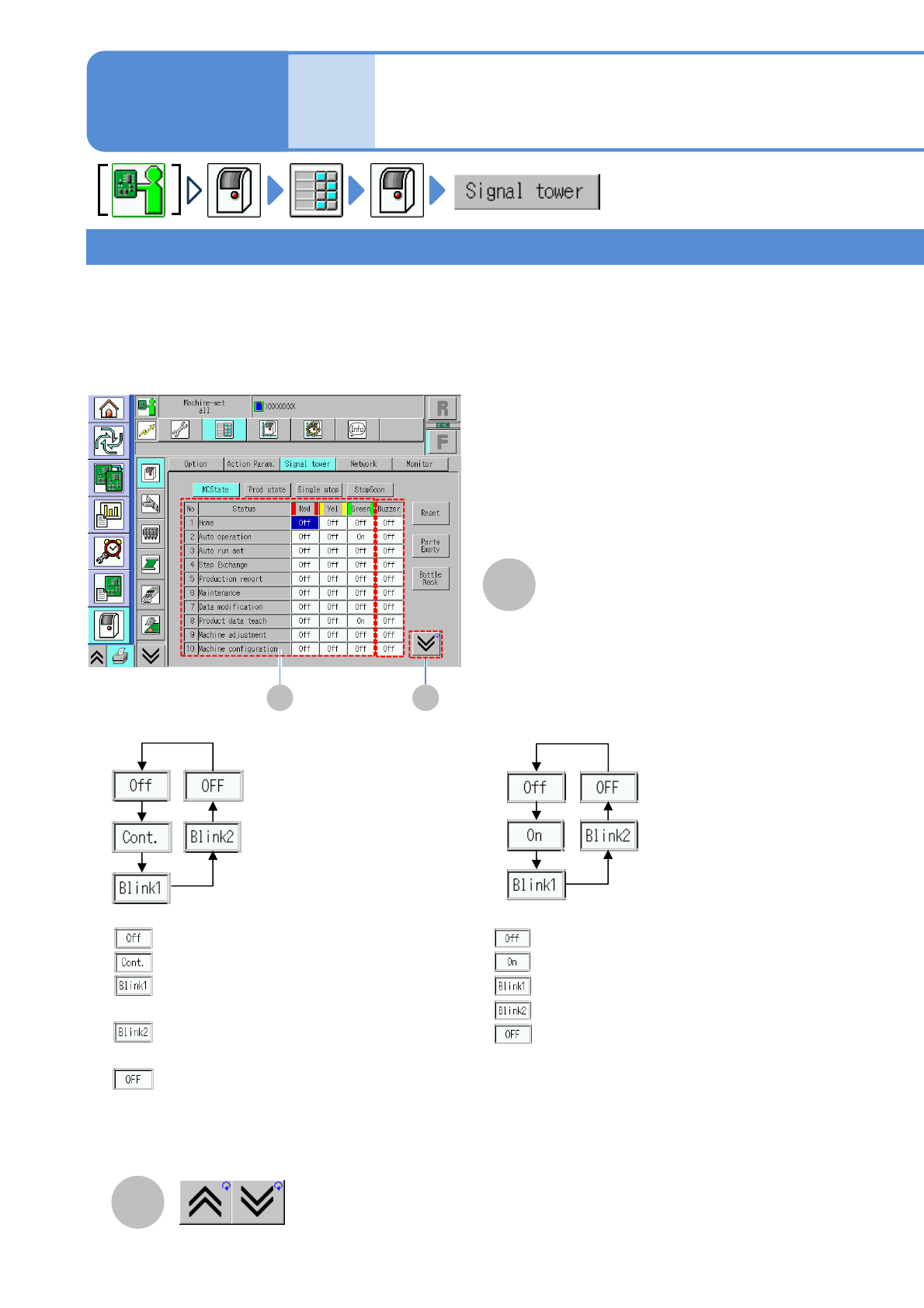
Signal tower setting 1
5-1-3-1
Operating procedure
5-1-3
●You can configure the indicator lamp and buzzer settings to fit various conditions.
Machine status/Production status/Single stop/Immediate stop
B
A B
●Choose the buzzer status
●Choose the status of red/yellow/green indicators
The previous or next table is
displayed.
A
Signal tower setting status
The signal tower and buzzer settings are divided into four categories; [MCState], [Prod state], [Single stop]
and [Stop Soon].
If several “conditions” occur in the machine, the setting of an item which has the highest priority is reflected to
the signal tower and buzzer condition.
“No.”: Sequence number
“Condition”: Item to set signal
:Buzzer does not produce sound
:Buzzer produces continuous sound
:Buzzer produces sounds at long interval
(in one second interval)
:Buzzer produces sound at short interval
(in 0.5 seconds interval)
:Buzzer condition is not changed.
1)
:Lamp turns off
: Lamp turns on
: Lamp blinks (in one second interval)
: Lamp blinks (in 0.5 seconds interval)
: Lamp condition is not changed
*1)
*1) The setting of an item which has second priority is being kept.
Ex) The condition changes to “None” while the red lamp setting is “Blink 1”, the red lamp condition is kept
as “Blink 1”.