N7201A652E.pdf - 第460页
NPM- TT2 EJM1E E-MB-05O-05 Nozzle position Offset of the selected nozzle is displayed in . 5-3-6 Machine parame- ter C B 設備に設置されている フィーダー の メモリー 情報 を 表示します 。 Checking offset per head angle You can check the X/Y/ θ elemen…
NPM-TT2 EJM1EE-MB-05O-05
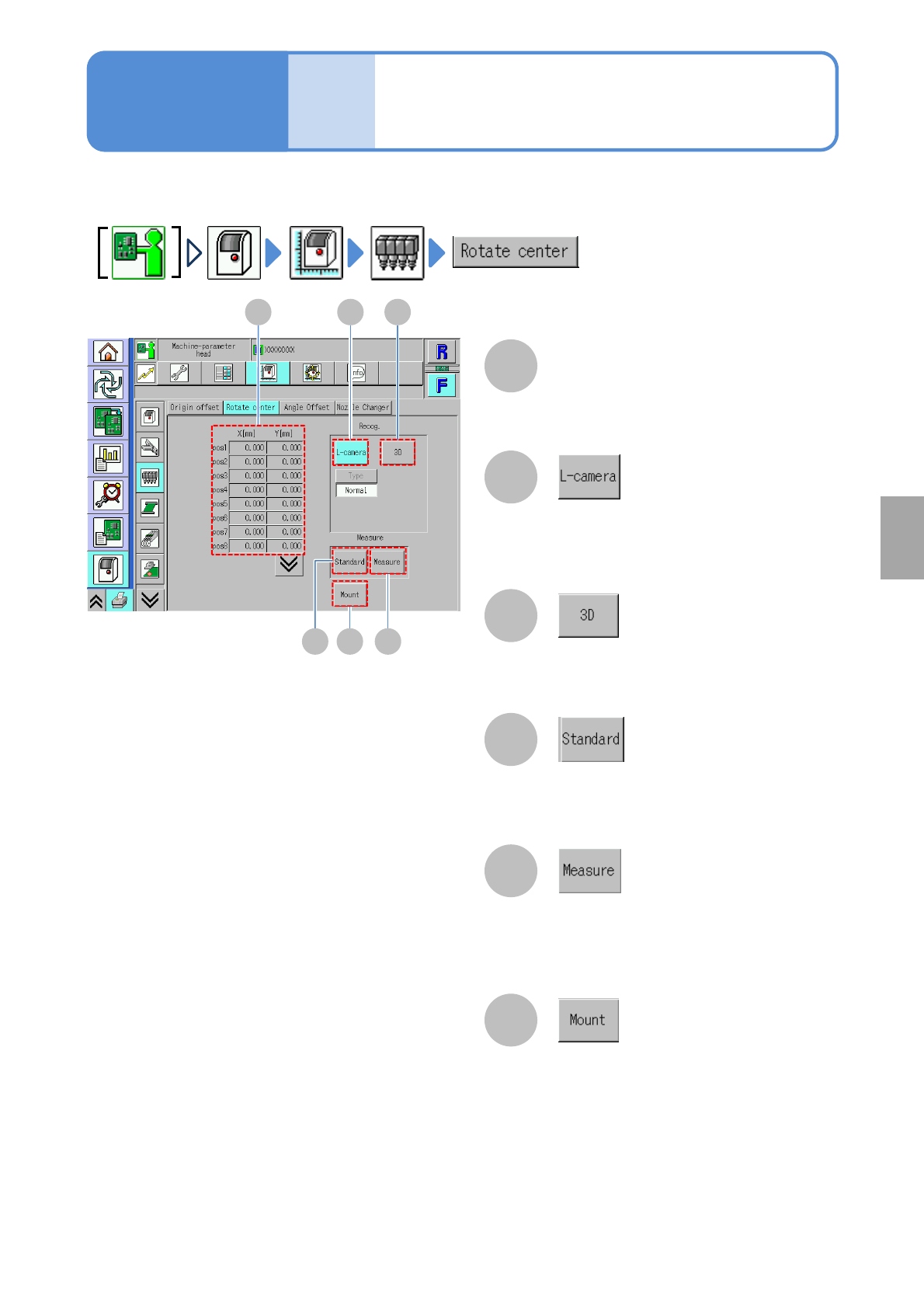
You can check rotation center offset (calibration result) of each nozzle head.
5-3-5
Machine
parame-
ter
Head rotation center
check
Operating procedure
5-3-5
System
administration
B
A
F
C
D
E
Switches the display of [Rotate center]
to the value used in recognizing
components with the line camera.
Rotate center X[mm]/Y[mm]
XY coordinates of rotation center.
Switches to the value being temporarily
retained after measurement.
Standard value of rotation center that is
used in correcting temporal changes.
Switches the display of [Rotate center] to
the value used in mounting the 3D
sensor.
Amount of change in the reference
rotation center that occurs during
temporal change correction.
A B C
E FD
NPM-TT2 EJM1EE-MB-05O-05
Nozzle position
Offset of the selected nozzle is displayed
in .
5-3-6
Machine
parame-
ter
C
B
設備に設置されているフィーダーのメモリー情報を表示します。
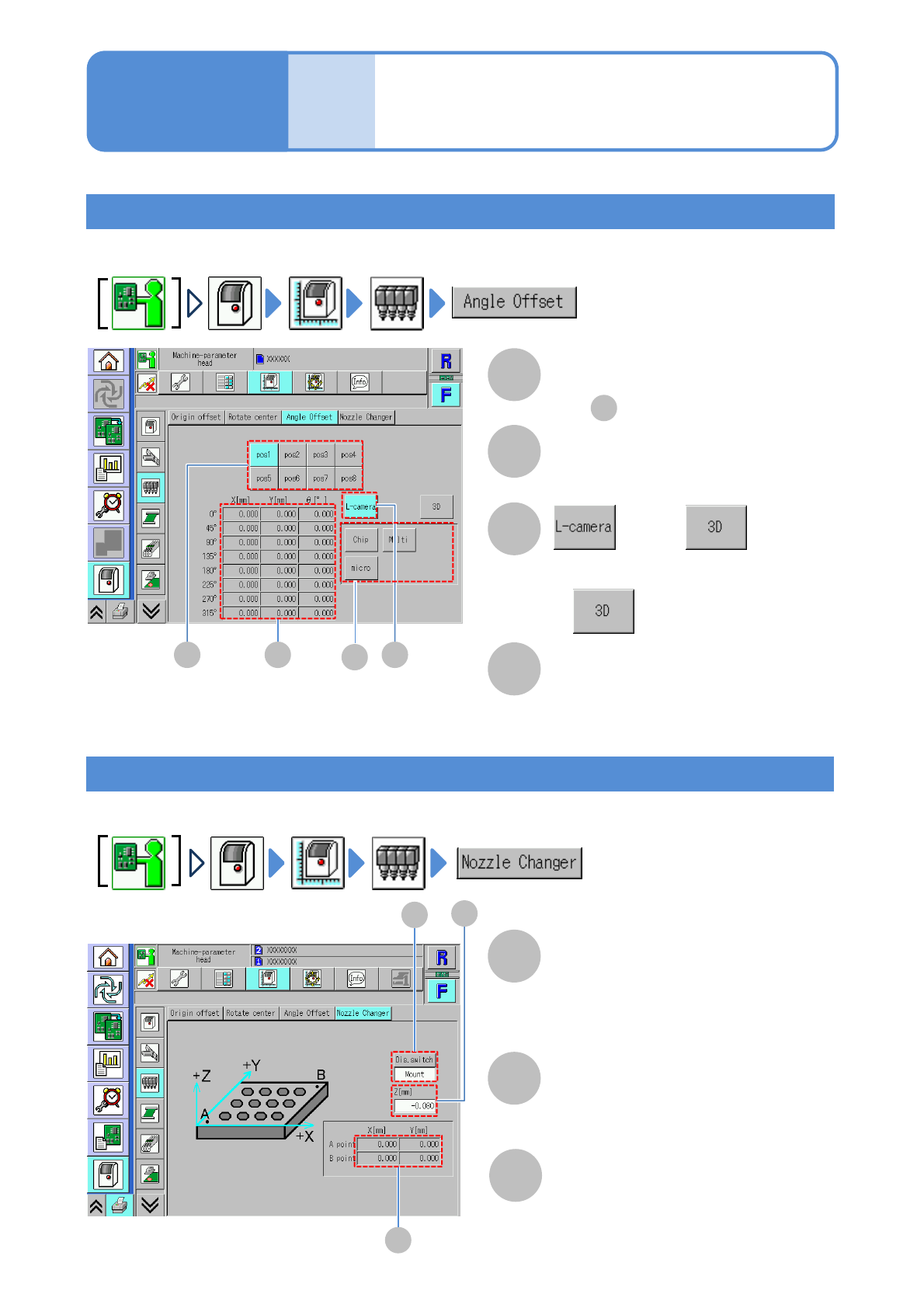
Checking offset per head angle
You can check the X/Y/θ element offset values (calibration result) per head θ rotation angle.
B CA
A
Checking height direction offset of the changer
You can check the nozzle changer height offset (calibration result).
B
C
D
D
A
Operating procedure
5-3-6
Offset per head angle
X[mm]/Y[mm]/ θ[°]
Offset values of X/Y coordinates and θ.
or
Switches to the line camera data.
● is used for the 8-/3-nozzle
heads.
Nozzle changer height Z[mm]
Height direction offset of the nozzle
changer.
Coordinates of A/B points
X[mm]/Y[mm]
Component selection
Offset per head angle
/changer height check
A
C
B
A
Display switch
Switches parameter display of the
nozzle changer for placement (Mount) or
the nozzle changer for support pins
(Support)
NPM-TT2 EJM1EE-MB-05O-05
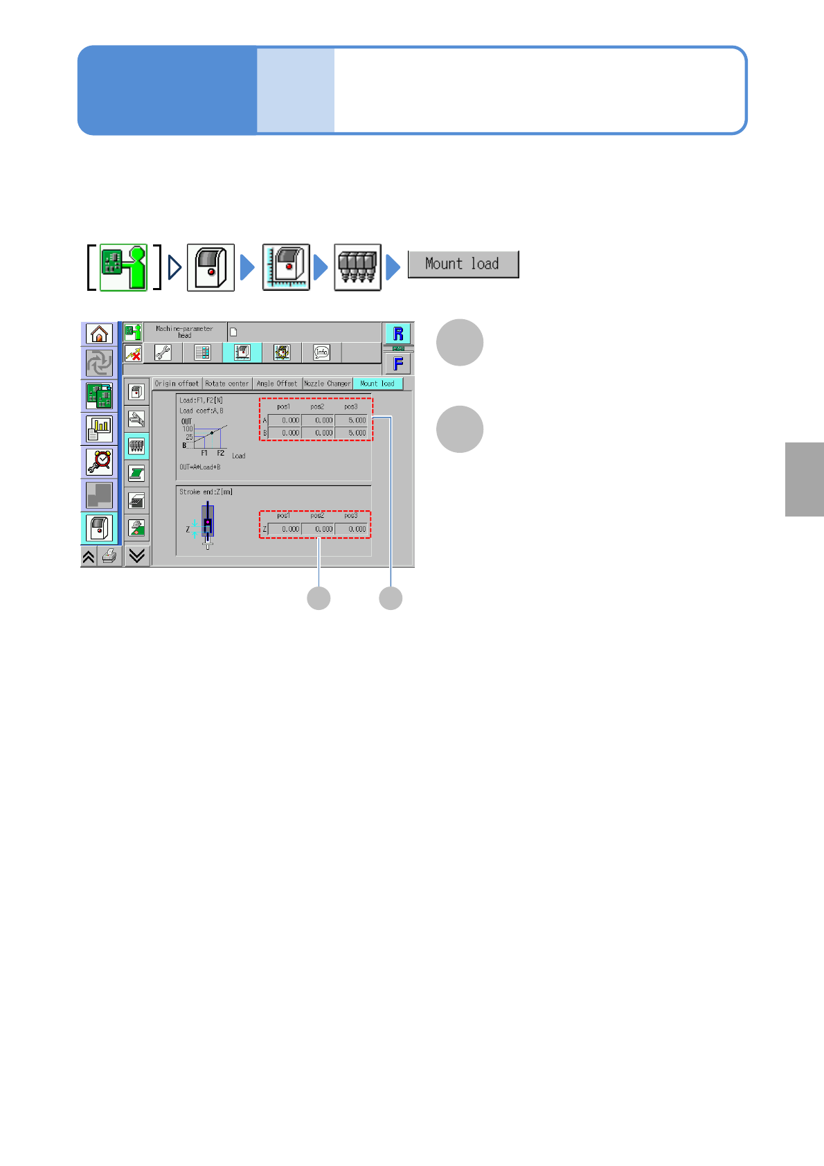
You can check the coefficient to apply the placement load of the head set in Load teaching
(→[Maintenance] P. 12-8-1 ).
●It is available only for 3-nozzle head.
5-3-7
Machine
parame-
ter
Head placement load
coefficient check
A
AB
B
Operating procedure
5-3-7
Load coef
Load coefficients A and B per nozzle
position.
Stroke end
Stroke end per nozzle position.
System
administration