N7201A652E.pdf - 第478页
NPM- TT2 EJM1E E-MB-06O-04 Specifi- cation Mac hine specifica tions/ Basic perf or mance 4 6-1-1 -7 Operating procedure 6-1-1 Recognition unit configuration 2 Connector recognition condition (T ype 1 ) General con dition…
NPM-TT2 EJM1EE-MB-06O-04
6-1-1-6
At
a glance
BGA / CSP recognition condition (Type 1 )
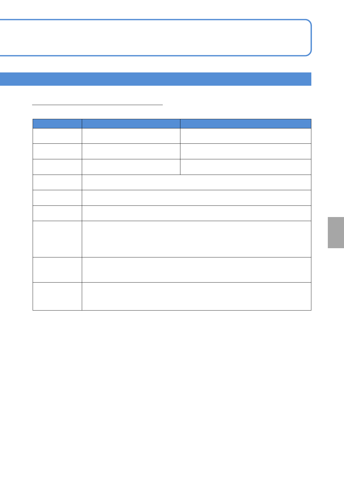
Conditions of BGA and CSP which can be placed are as follows:
*1)
8-nozzle head 3-nozzle head
Outer dimensions 2 x 2 to 32 x 32 mm
*2)
2 x 2 to 90 x 90 mm
*2) *3)
Thickness 0.3 to 12 mm 0.3 to 30 mm
Ball pitch 0.4
*2)
to 1.5 mm 0.3
*2)
to 1.5 mm
Ball diameter φ0.15 to φ0.9 mm
Ball shape Ball or cylinder type
*4)
Ball material High temperature solder or eutectic solder
Maximum
number of balls
4096 balls
For positive-grid arrangement: (The number of rows x the number of columns) in the
outermost region is (64 x 64) balls
For staggered arrangement: (The number of rows x the number of columns) in the
outermost region is (32 x 32) balls
Minimum number
of balls
9 balls
(The number of rows x the number of columns) in the outermost region is (3 x 3) balls
Ball arraignment The balls should be uniform in pitch and size.
*5)
Supply type: Tape, tray
・The recognition of the outer shape of BGA / CSP and the simultaneous recognition of solder balls are
intended for those whose body is made of glass epoxy.
Recognition may be difficult depending on the condition of the solder ball placement surface (presence of
patterns / through holes, gloss, etc.).
・Those whose body is made of ceramic, or whose body color is gold, are placed by using the outer shape
recognition only.
・Keep the ball surfaces from becoming cloudy or turbid due to oxidation. You need to experimentally confirm
what degree of oxidation affects the availability of recognition.
*1) Basically, assess the availability of recognition by reviewing / conducting experimental placement using
samples.
*2) Consult us for large-sized fine-pitch components.
*3) If outer dimensions of a component exceeds 45 45 mm, split recognition is performed. (Recognition
range: 80 x 80 mm)
*4) Certain combinations of 2 ball pitches and ball diameters may make it impossible for you to perform
placement.
*5) The same Ball Miss and Plover pattern that are provided in the JEDEC and EIAJ with respect to BGA /
CSP are used.
●For components outside the above specifications, contact us.

NPM-TT2 EJM1EE-MB-06O-04
Specifi-
cation
Machine specifications/
Basic performance 4
6-1-1-7
Operating procedure
6-1-1
Recognition unit configuration 2
Connector recognition condition (Type 1 )
General conditions of a connector which can be placed are as follows
*1)
.
8-nozzle head
3-nozzle head
Outer dimensions 32 x 32 mm or less
L 120 x W 90 mm or less
*2) *3)
L 150 x W 25 mm or less
*2)
Lead pitch 0.5 mm or more
Lead width 0.2 mm or more
Lead shape The amount of lead protrusion from the body should be 1 mm or more.
Other shape
There should be no through holes in a vertical direction around contact pins.
Contact pins should not be exposed on the under surface.
Supply type: Tape, tray, stick
*1) Basically, assess the availability of recognition by reviewing / conducting experimental placement using
samples.
*2) In the case of placement of a large connector, its size may be limited due to a relationship between the
pickup position and the camera view as well as this condition.
For details, contact us.
*3) If outer dimensions of a component exceeds 45 45 mm, split recognition is performed.
NPM-TT2 EJM1EE-MB-06O-04
6-1-1-8
At
a glance
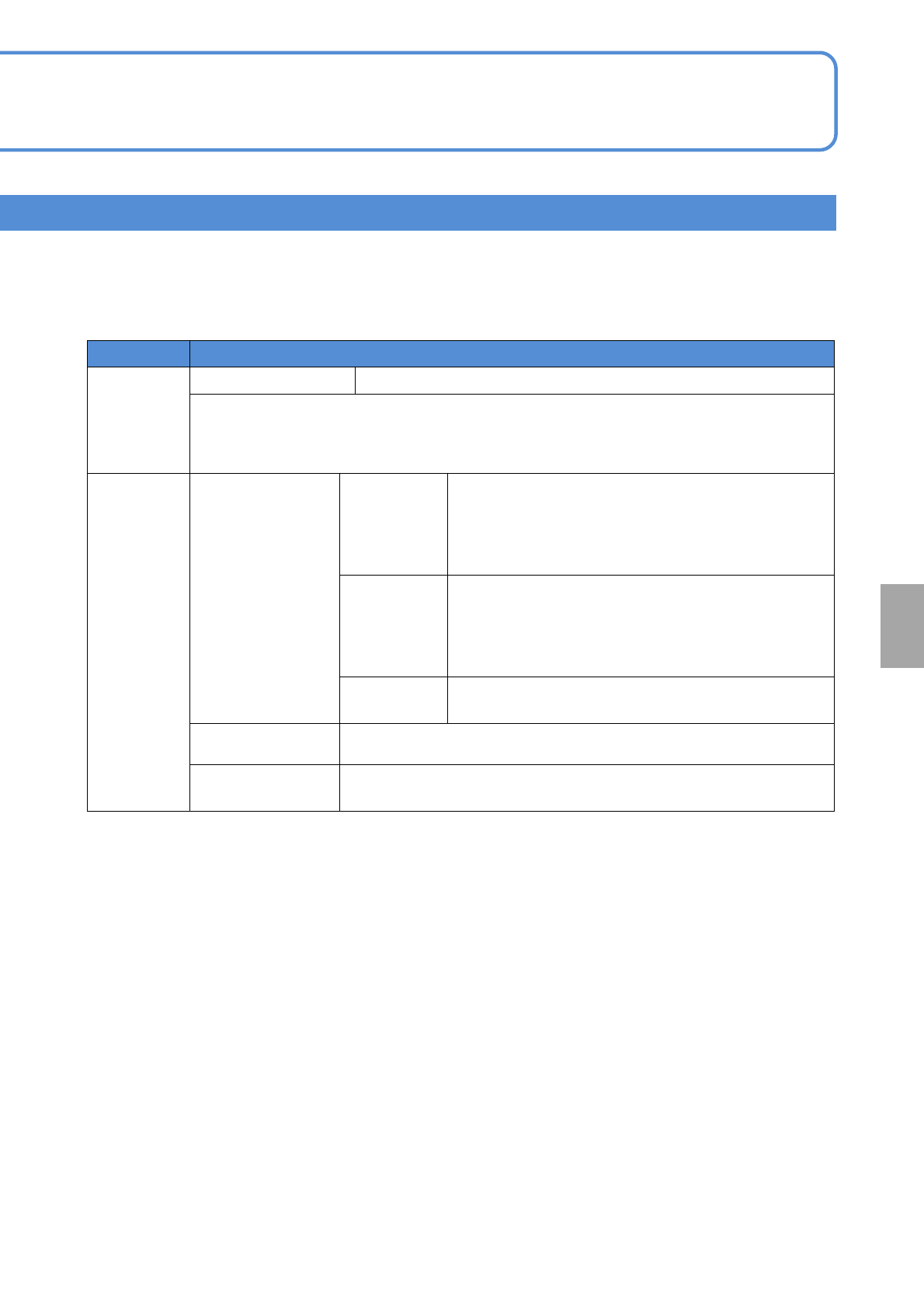
■Part thickness measurement function (Multi-recognition camera: [Type 2])
Item Description
Applicable
component
Each time 0402 to Mini Tr / Di
Minimum part thickness: 0.1 mm
*To detect the pickup of a component being in a standing or slanted position, the difference
between any two of the following --- the thickness, width and length of the component ---
needs to be at least 50 μm.
Function
Part thickness
measurement
function
Each time
Part thickness is measured each time, which is
reflected in placement height. In addition, you can
simultaneously check the pickup of micro parts being
in a standing or slanted position and the reversing
pickup of Tr / Di.
At the time of
first pickup
after
component
changes
Thickness measurement is done for first pickups after
“Automatic operation start”, “Component replenishment
following exhaustion detection”, “Tape splicing
detection”,and “Chip data modify.”
Part teaching
You can make thickness measurement and chip data
entry on a per-part basis.
Nozzle top check
function
Checks the height of the nozzles for abnormalities.
*1)
Eject detection
function
If an error such as a recognition error has occurred, it checks the top of
the nozzles for any extraneous / foreign matter after ejecting parts.
・This is not applicable to the measurement of nozzles with a pad or nozzles (e.g., 205A) the top of which is
dished.
・Purchase on a per-table (front / rear) basis.
*1) Breaks, sliding failures in nozzle holders
Multi-recognition camera: For type 2, in addition to the function in type 1, it equips with the part thickness
measurement and flip-over detection function to improve placement quality.
●Regarding the machines released later than NPM-D3 / NPM-W2 / NPM-TT2 and equipped with multi-
recognition camera, the component library for the conventional line camera may not be partially compatible.
(When the function such as illuminance check of recognition option is used)