N7201A652E.pdf - 第481页
NPM- TT2 EJM1E E-MB-06O-04 6-1-1 -10 At a glance BGA / CSP recognition condition (T ype 3 ) Conditions of BGA / CSP which can be placed are as follows *1) . 8-nozzle head 3-nozzle head Outer dimensions 2 x 2 to 32 x 32 m…
NPM-TT2 EJM1EE-MB-06O-04
Specifi-
cation
Machine specifications/
Basic performance 5
6-1-1-9
Operating procedure
6-1-1
■3D measurement function (multi-recognition camera: [Type 3])
Multi-recognition camera: For type 3, in addition to the function in type 2, it is possible to detect the coplanarity
and XY-directional position of all leads such as the ones of QFP / SOP and the at a high speed.
Presence / absence or chipping of each ball on BGA / CSP can be detected.
Recognition
method
Recognition
speed
Example of
applicable
components
Minimum lead /
Minimum ball pitch
Minimum lead
width /
Minimum ball
diameter
Minimum ball
height
Batch
recognition
3D high speed
QFP, SOP 0.4 mm
*1)
0.12 mm ―
BGA, CSP 0.5 mm
*2)
0.3 mm 0.25 mm
*1) For QFP/ SOP whose lead pitch is 0.4 mm or less, consult us.
*2) For CSP whose ball pitch is 0.5 mm or less, consult us.
QFP recognition condition (Type 3)
Conditions of QFP which can be placed are as follows
*1)
.
8-nozzle head
3-nozzle head
Outer dimensions 2 x 2 to 32 x 32 mm 2 x 2 to 80 x 80 mm
*2)
Thickness 1.0 to12 mm 1.0 to 30 mm
Lead pitch 0.4 mm, 0.5 mm, 0.65 mm, 1.0 mm, 1.27 mm, 1.5 mm
Lead width 0.2 mm or longer
Lead shape The amount of lead protrusion from the mold should be 1 mm or more.
Supply type: Tape, tray
・The measurement range of lead coplanarity is ±0.5 mm.
・The planar portion of the lead under surface needs to be 0.2 mm or more in length.
・Depending on the recognition speed or the number of leads, it may take a certain amount of time to wait for
recognition processing at the time of placement.
*1) Basically, assess the availability of recognition by reviewing / conducting experimental placement using
samples.
*2) If outer dimensions of a component exceeds 45 45 mm, split recognition is performed.
●For details, contact us.
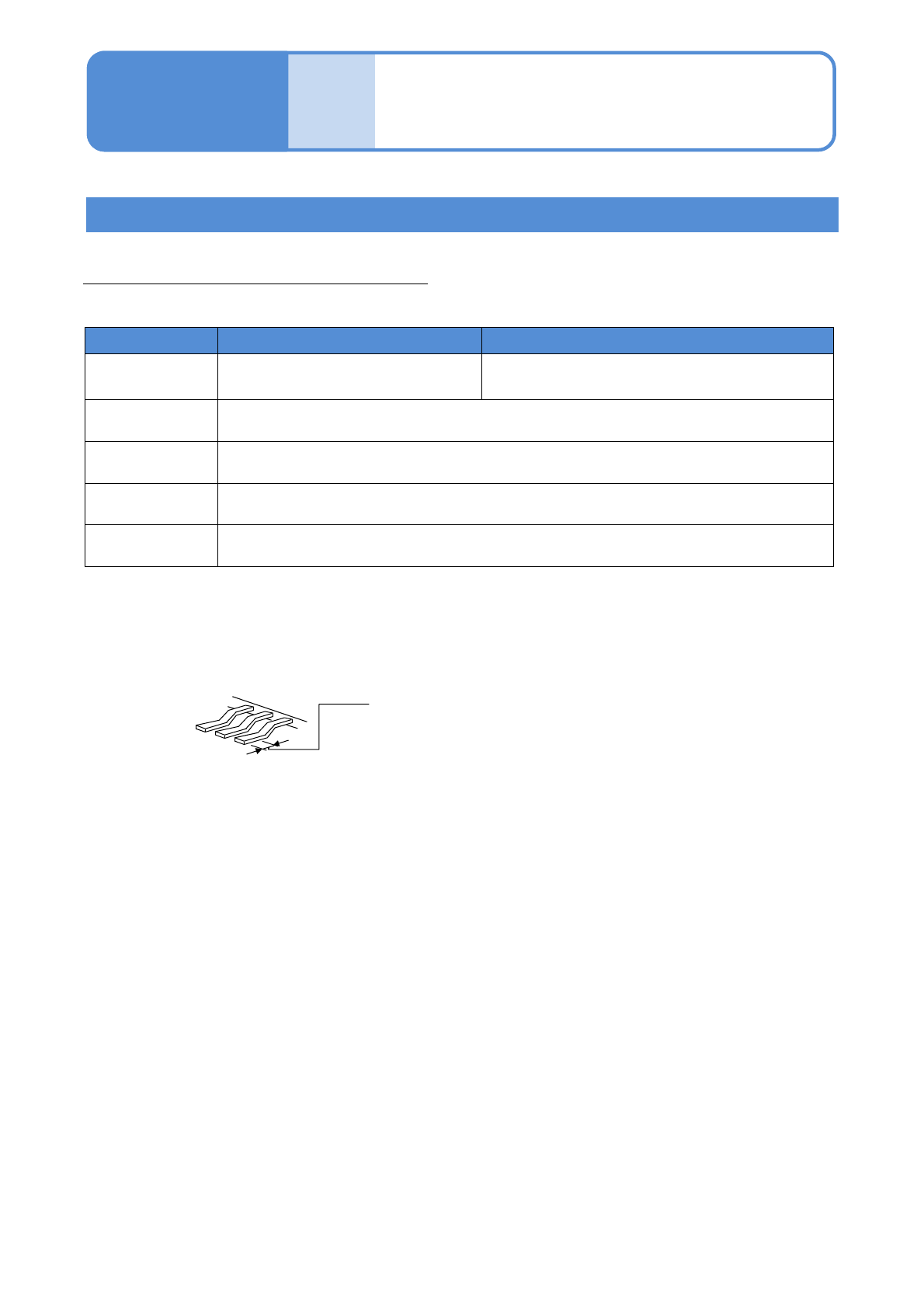
The planar portion of the under surface
0.2 mm or more
Recognition unit configuration 3
●Regarding the machines released later than NPM-D3 / NPM-W2 / NPM-TT2 and equipped with multi-
recognition camera, the component library for the conventional line camera may not be partially compatible.
(When the function such as illuminance check of recognition option is used)
NPM-TT2 EJM1EE-MB-06O-04
6-1-1-10
At
a glance
BGA / CSP recognition condition (Type 3 )
Conditions of BGA / CSP which can be placed are as follows
*1)
.
8-nozzle head 3-nozzle head
Outer dimensions 2 x 2 to 32 x 32 mm 2 x 2 to 90 x 90 mm
*2)
Thickness 0.3 to 12 mm 0.3 to 30 mm
Minimum ball
pitch
0.5 mm 0.4 mm
Minimum ball
diameter
φ0.3 mm φ0.25 mm
Ball shape Ball
Ball material High temperature solder or eutectic solder
Number of balls 2 x 2 to 64 x 64 balls
Ball arrangement The balls should be uniform in pitch and size.
*3)
Supply type: Tape, tray
・Some ball surface conditions may prevent recognition.
・The supply type applies to those that have ball-shaped terminals on their under surface side.
・ Depending on the recognition speed or the number of leads, it may take a certain amount of time to wait
for recognition processing at the time of placement.
・ When the reflecting light is illuminated or the reflecting lamp offset value is set, the ball height inspection is
not performed.
*1) Basically, assess the availability of recognition by reviewing / conducting experimental placement using
samples.
*2) If outer dimensions of a component exceeds 45 45 mm, split recognition is performed. (Recognition
range: 80 x 80 mm)
*3) The same Ball Miss and Alternate pattern that are provided in the JEDEC and EIAJ with respect to BGA /
CSP are used.
●For details, contact us.
NPM-TT2 EJM1EE-MB-06O-04
Specifi-
cation
Machine specifications/
Basic performance 6
6-1-1-11
Operating procedure
6-1-1
Connector recognition condition (Type 3 )
General conditions of a connector which can be placed are as follows
*1)
.
8-nozzle head
3-nozzle head
Outer dimensions 32 x 32 mm or less
L 120 x W 90 mm or less
*2) *3)
L 150 x W 25 mm or less
*2)
Lead pitch 0.5 mm or more
Lead width 0.2 mm or more
Lead shape The amount of lead protrusion from the body should be 1 mm or more.
Other shape
There should be no through holes in a vertical direction around contact pins.
Contact pins should not be exposed on the under surface.
*1) Basically, assess the availability of recognition by reviewing / conducting experimental placement using
samples.
*2) In the case of placement of a large connector, its size may be limited due to a relationship between the
pickup position and the camera view as well as this condition.
*3) If the recognition area exceeds W 45 mm but not exceed 80 mm, split recognition is performed.
●For details, contact us.
Supply type: Tape, tray, stick
・The measurement range of lead coplanarity is ±0.5 mm.
・The planar portion of the lead under surface needs to be 0.2 mm or more in length
The planar portion of the under surface
0.2 mm or more
・Recognition may fail under certain under surface conditions of leads.
Recognition unit configuration 4