N7201A652E.pdf - 第483页
NPM- TT2 EJM1E E-MB-06O-04 6-1-2 At a glance Specifi- cation PCB flo w dir ection Operating procedure 6-1-2 Dual conveyor Fixed rail Front Left-to-right flow, Front reference Front Right-to-left flow, Front reference Lef…
NPM-TT2 EJM1EE-MB-06O-04
Specifi-
cation
Machine specifications/
Basic performance 6
6-1-1-11
Operating procedure
6-1-1
Connector recognition condition (Type 3 )
General conditions of a connector which can be placed are as follows
*1)
.
8-nozzle head
3-nozzle head
Outer dimensions 32 x 32 mm or less
L 120 x W 90 mm or less
*2) *3)
L 150 x W 25 mm or less
*2)
Lead pitch 0.5 mm or more
Lead width 0.2 mm or more
Lead shape The amount of lead protrusion from the body should be 1 mm or more.
Other shape
There should be no through holes in a vertical direction around contact pins.
Contact pins should not be exposed on the under surface.
*1) Basically, assess the availability of recognition by reviewing / conducting experimental placement using
samples.
*2) In the case of placement of a large connector, its size may be limited due to a relationship between the
pickup position and the camera view as well as this condition.
*3) If the recognition area exceeds W 45 mm but not exceed 80 mm, split recognition is performed.
●For details, contact us.
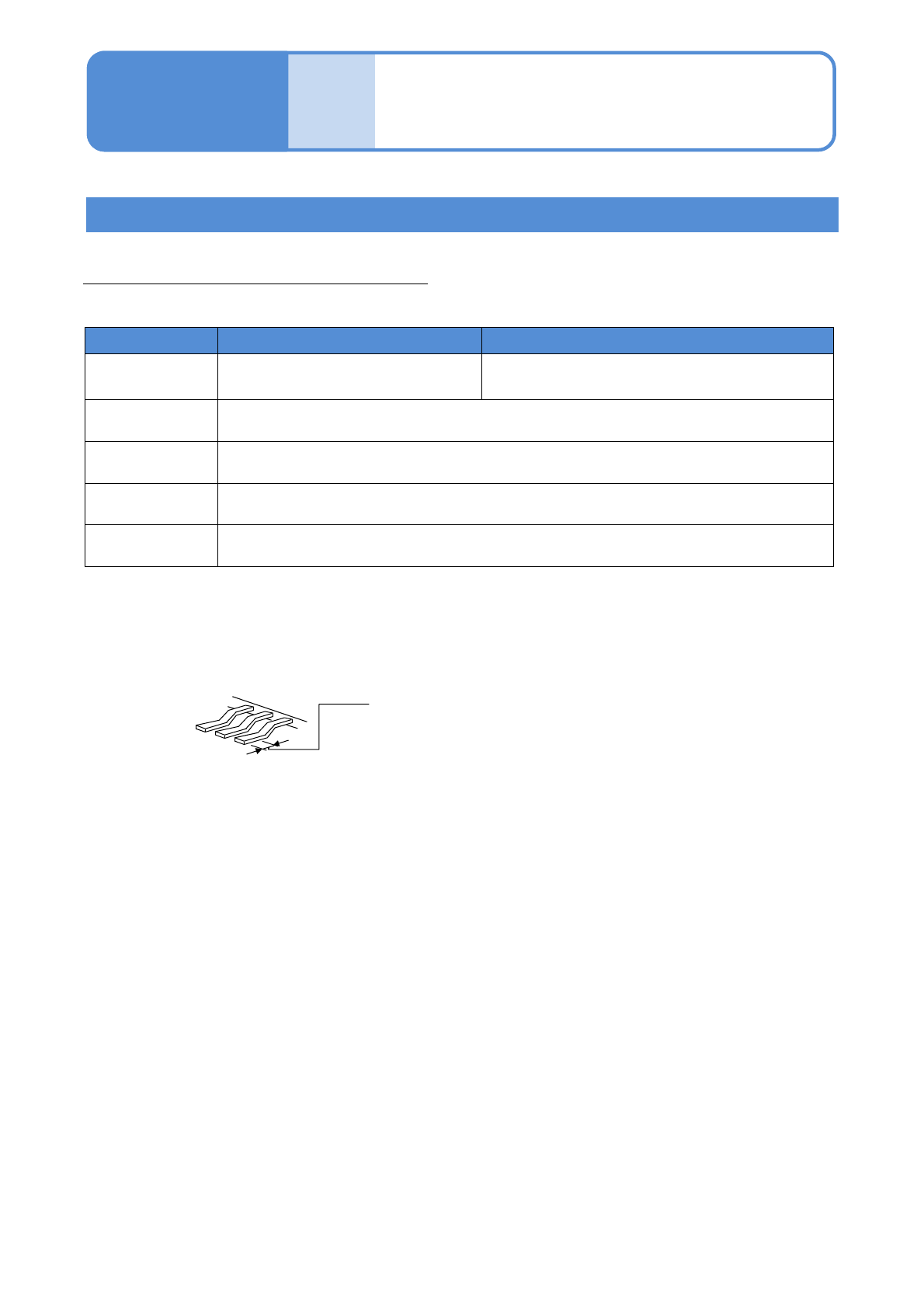
Supply type: Tape, tray, stick
・The measurement range of lead coplanarity is ±0.5 mm.
・The planar portion of the lead under surface needs to be 0.2 mm or more in length
The planar portion of the under surface
0.2 mm or more
・Recognition may fail under certain under surface conditions of leads.
Recognition unit configuration 4
NPM-TT2 EJM1EE-MB-06O-04
6-1-2
At
a glance
Specifi-
cation
PCB flow direction
Operating procedure
6-1-2
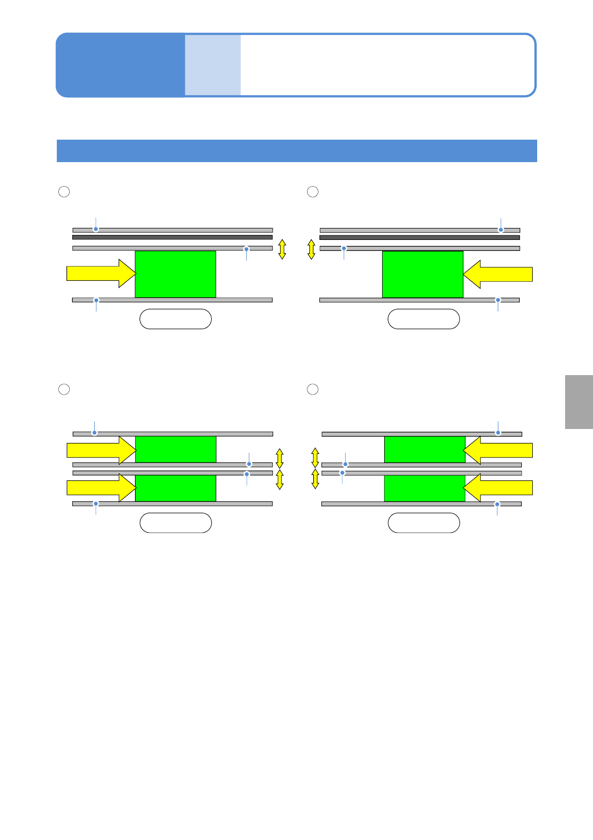
Dual conveyor
Fixed rail
Front
Left-to-right flow, Front reference
Front
Right-to-left flow, Front reference
Left-to-right flow Right-to-left flow
Movable rail
■Single lane mode
■Dual lane mode
1 2
1 2
PCB flow
Fixed rail
PCB flow
Movable rail
Fixed rail
Front Front
Movable rail
PCB flow
Fixed rail
Movable rail
Fixed rail
Movable rail
Fixed rail
PCB flow
Fixed rail
Movable rail
Fixed rail
PCB flow PCB flow
NPM-TT2 EJM1EE-MB-06O-04
Specifi-
cation
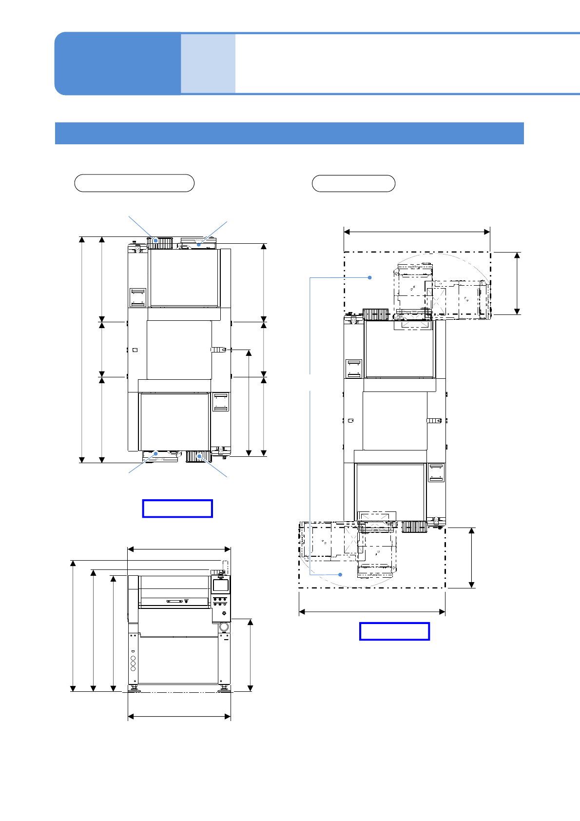
Outside dimensions
and working area 1
Operating procedure
6-1-3
Single tray specifications
(Unit: mm)
■When the single tray feeder is connected
Outside dimensions
Working area
13-slot supply
unit
Single tray
feeder
13-slot supply
unit
Single tray
feeder
971686971
1 314
1 0566861 056
2 798
作業
エ
リア
1 831
763
作業
エリ
ア
Working area
763
1 831
900
1 514
1 629
1 265(cover outline)
1 280(conveyor width)
1 444
6-1-3-1
Front side
Front side