N7201A652E.pdf - 第63页
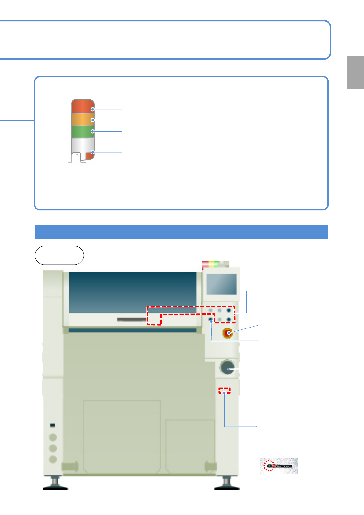
NPM- TT2 EJM1EE-SF-01N-05 Operating units Emergency stop switch Stops ope ration immediately Main power supply switch (Front side) Turns ON/OFF the power and air sour ce.(When you turn off the powe r supp ly switch, the …
NPM-TT2 EJM1EE-SF-01N-05
Com-
ponent
names
Appearance
diagram/Operating units
Front side
Rear side
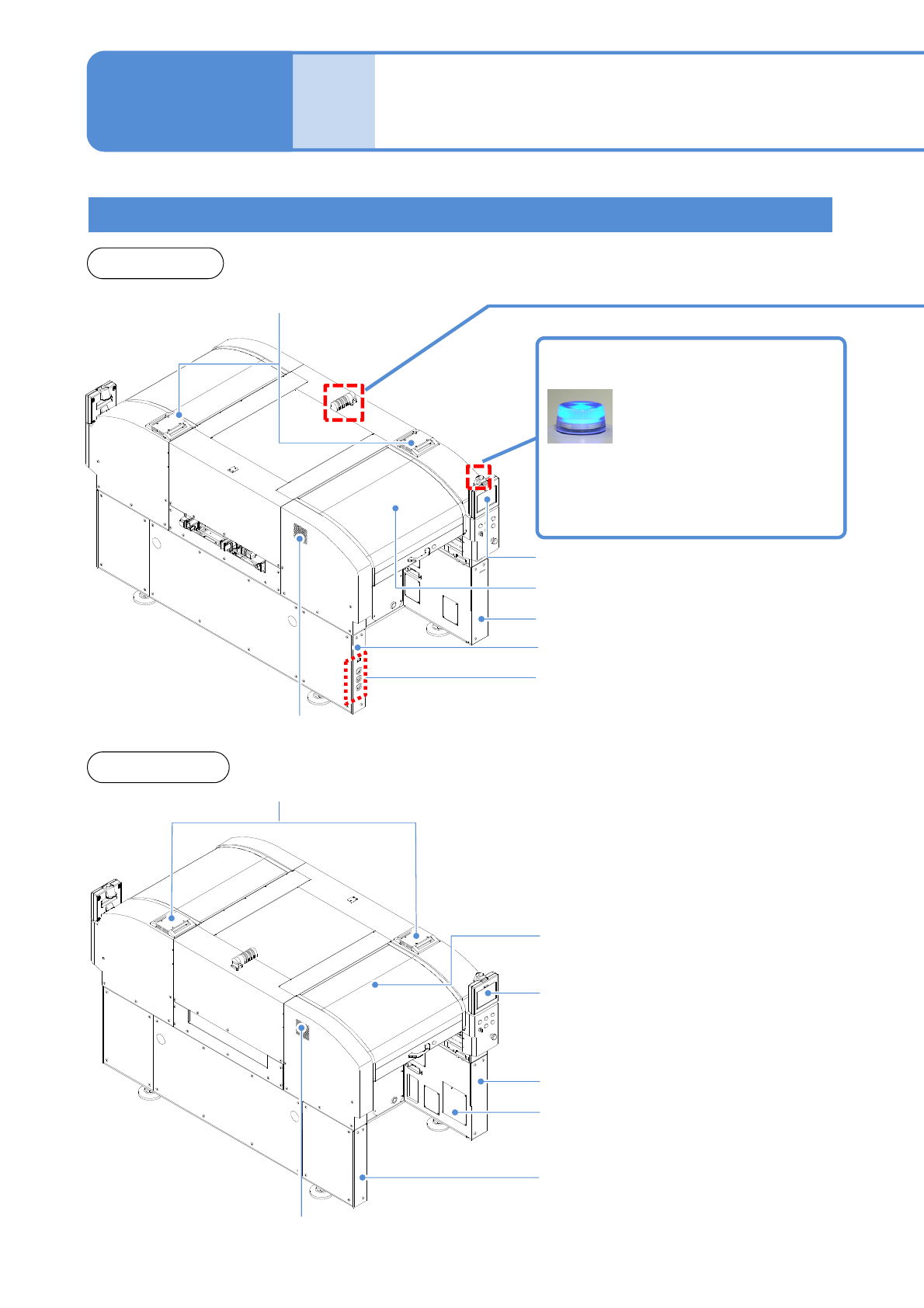
Appearance diagram
1-9-1-1
1-9-1
Component empty lamp
Automatic run
Outlet
Inlet
Outlet
Inlet
Light OFF: Normal run
Light ON: Components have
run out
Flashing: Shortage of component
Safety cover (Front side)
Touchscreen (Front side)
Safety cover (Rear side)
Touchscreen (Rear side)
Regulator cover (Rear side)
Various pressure gauges
Regulator cover (Front side)
Cover (Front side)
Cover (Rear side)
Power supply cover (Rear side)
NPM-TT2 EJM1EE-SF-01N-05
Operating units
Emergency stop
switch
Stops operation
immediately
Main power supply
switch (Front side)
Turns ON/OFF the power and
air source.(When you turn off
the power supply switch, the
air supply is shut off also.)
1-9-1-2
Signal tower
Red: Illuminates when you push emergency stop switch or in case
of error stop.
Yellow: Illuminates in case of material shortage.
Green: Illuminates in automatic operation.
Red: Illuminates when you push emergency stop switch or in case
of error stop.
● You can change the above setting.
[Operating Procedure] (→ P.5-1-3)
● Please refer to the [Operating Procedure] (→P.5-2-4)
●The signal tower is placed sideways when shipped , however the angle can be adjusted.
Front and
rear sides
Various operation
switches
Controls operation start /
stop.
Access lamp
(Green LED)
SD card reader
(Front side)
Reading and writing of
programming data.
Servo switch
Turns ON/OFF the
power of servo units.
Confirmation
NPM-TT2 EJM1EE-SF-01N-05
Com-
ponent
names
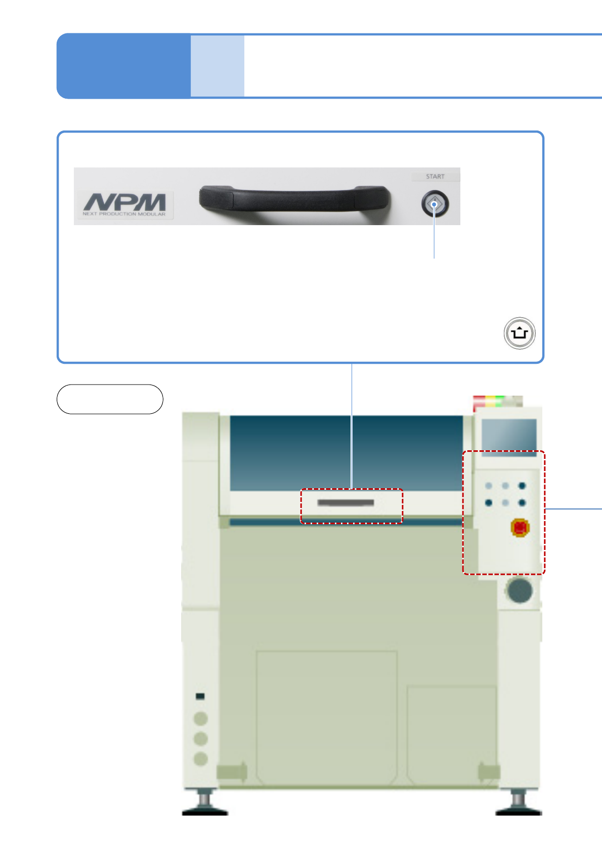
Operation switch
1-9-2-1
1-9-2
START
Starts production.
●Restarts production when in
temporary stop.
●Push the button with
at the same time
Front and
rear sides