User Manual SIPLACE Linear Dipping Unit 2 X.pdf - 第50页
4 Operation 4.1 Settings in SIPLACE Pro 50 User Manual SIPLACE Linear Dipping Unit 2 X 05/2020 4.1.8 Setting the cavity depth and the pressing force To obtain a good coating of a component with flux, a suitable cavity de…
4 Operation
4.1 Settings in SIPLACE Pro
User Manual SIPLACE Linear Dipping Unit 2 X 05/2020 49
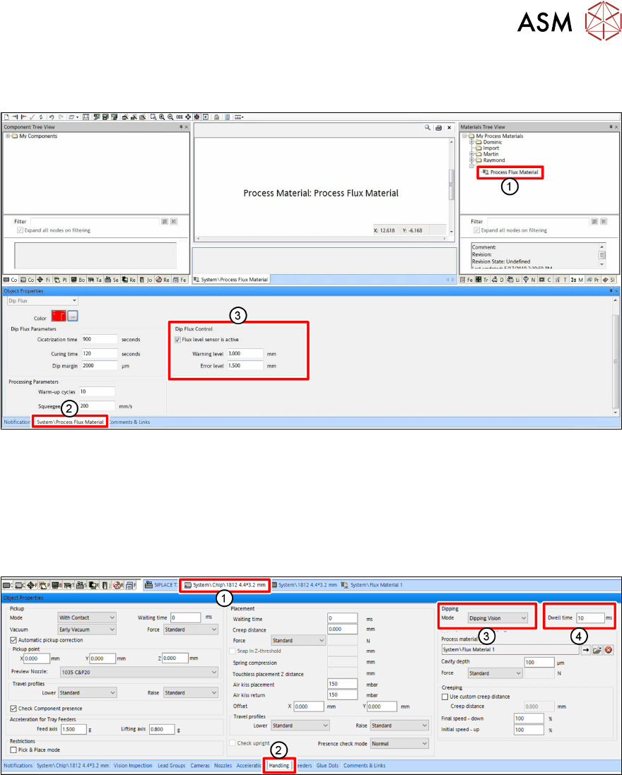
4.1.6 Setting the Flux Level Sensor parameters
The parameters for the Flux Level Sensor are flux-specific:
► In SIPLACE Pro, select the flux material (1) from the Materials Tree View.
► Click on the tab of the flux material (2) to display its properties in the editor.
► In the Dip Flux Control area (3), mark Flux level sensor is active to activate the flux level
sensor for this particular flux material.
► Enter the appropriate values for the Warning level and the Error level.
4.1.7 Setting the dipping sequence and the dwell time
► In SIPLACE Pro, click on the tab of the component shape of the desired component(1).
► Click on the Handling tab(2) in the Object Properties view.
► Select the dipping sequence under Mode(3) in the Dipping area.
► Enter the dwell time in milliseconds[ms] in the Dwell time field (4).
For more information on the dwell time, see chapter 3.3.6 "Dipping process and dwell time" [}38].
For more information on the different dipping sequences, see the online help of the line software.
4 Operation
4.1 Settings in SIPLACE Pro
50 User Manual SIPLACE Linear Dipping Unit 2 X 05/2020
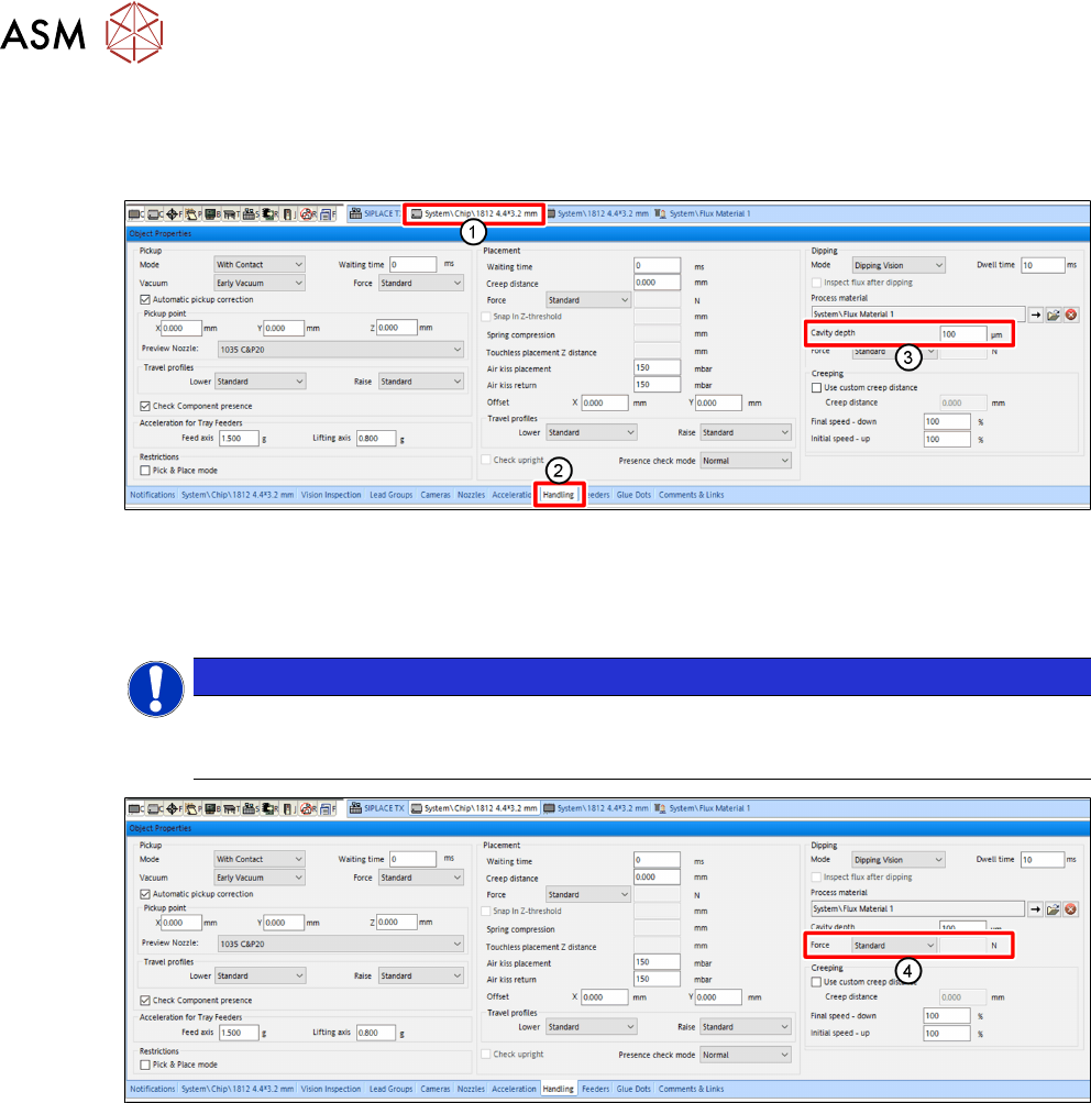
4.1.8 Setting the cavity depth and the pressing force
To obtain a good coating of a component with flux, a suitable cavity depth for dipping must be as-
signed to that component.
► In SIPLACE Pro, click on the tab of the component shape of the desired component(1).
► Click on the Handling tab(2) in the Object Properties view.
► In the Dipping area, enter the cavity depth in micrometers [µm] in the Cavity depth entry
field(3)
.
NOTICE
Ensure that your setup contains at least one combination of cavity depth and flux
that matches the dipping requirements for this component (see chapter 4.1.3
"As-
signing a dipping plate and a flux to the LDU" [
}
46]).
► In the Dipping area, from the Force menu (4), select the desired mode for the pressing force:
●
Standard
●
Specific
●
Very low
► If you select Specific, you can enter the desired pressing force in Newton [N] in the entry field
to the right.
4 Operation
4.1 Settings in SIPLACE Pro
User Manual SIPLACE Linear Dipping Unit 2 X 05/2020 51
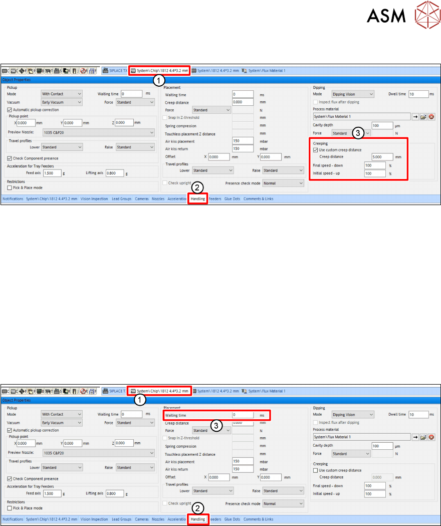
4.1.9 Setting the creep distance
► In SIPLACE Pro, click on the tab of the component shape of the desired component(1).
► Click on the Handling tab(2) in the Object Properties view.
► Enable the Use custom creep distance option(3) under Creeping(3) in the Dipping area.
► Enter the desired length of the creep distance in the Creep Distance entry field.
► In the Speed down end entry field, enter the desired speed down.
► In the Speed up start entry field, enter the desired speed up.
For more information to creep distance, speed down and speed up, see chapter 3.3.7 "Creep dis-
tance" [}38].
4.1.10 Setting the waiting time
Depending on the component and the flux used, it can be advantageous to hold the component on
the PCB for a short waiting time during the placement process.
► In SIPLACE Pro, click on the tab of the component shape of the desired component(1).
► Click on the Handling tab(2) in the Object Properties view.
► Enter the Waiting time in milliseconds [ms] in the Waiting Time entry field (3) in the Place-
ment area.