User Manual SIPLACE Linear Dipping Unit 2 X.pdf - 第64页
4 Operation 4.5 Checking the layer thickness 64 User Manual SIPLACE Linear Dipping Unit 2 X 05/2020 Performing the measurement Measurement 1 ► Hold the measuring device with your thumb and forefinger on its handle. ► (1)…
4 Operation
4.5 Checking the layer thickness
User Manual SIPLACE Linear Dipping Unit 2 X 05/2020 63
On one side of the rectangular measuring instrument there are engraved teeth with increasing spa-
cing from the contact surface. A scale is marked above the teeth and the engraved numbers indic-
ate the distance from the contact surface in µm. These measuring devices are usually made of
steel so that they can be cleaned with solvents.
Measurement principle
The measuring device is dipped into the layer of flux. The point at which the flux touches a tooth is
the layer thickness measurement (arrow in right-hand image).
Performing the measurement
► Place the measuring device onto the flux surface as shown above and press down to the base
of the cavity.
► Perform a brief "combing" movement while applying moderate pressure.
► Take the measuring device vertically up and out of the flux.
► Determine the shortest tooth which is coated by flux.
► Read the value on the scale at this point.
4.5.2 Layer thickness measurement "roller"
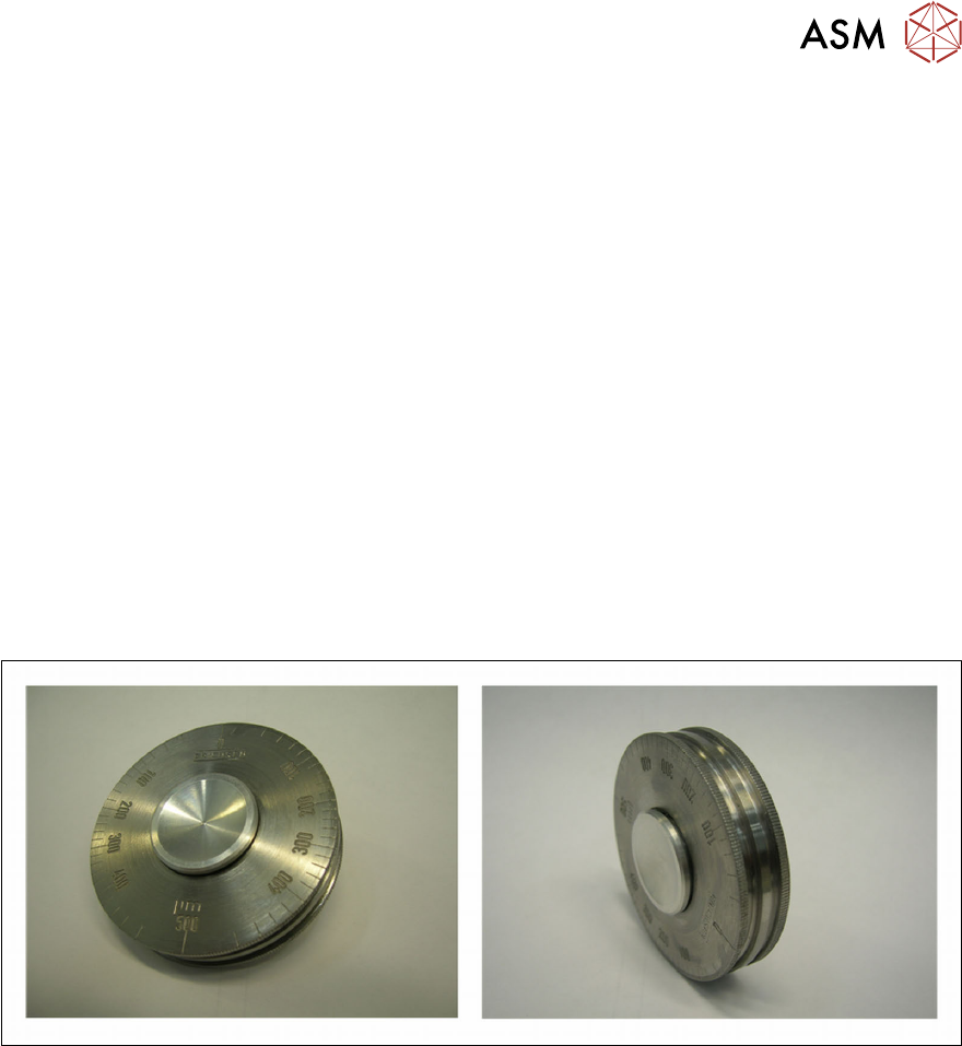
Structure of measuring device
The measuring device consists of a rotating handle and three rollers. The innermost roller has a
small diameter and runs eccentrically to the other two outer rollers. A scale is marked on the out-
side. These measuring devices are usually made of stainless steel so that they can be cleaned with
solvents.
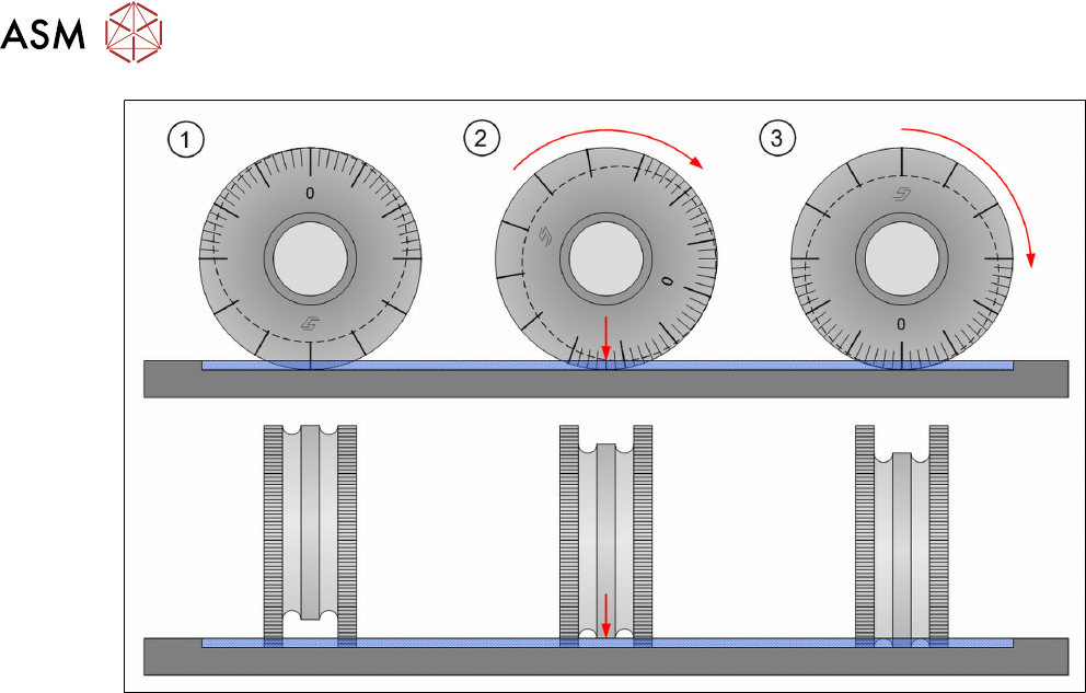
Measurement principle
The measuring device is rolled through the layer of flux. The two outer rollers moved on the base of
the cavity. The eccentrically aligned middle roller is rotated and guided towards the surface of the
flux. The point at which the flux touches this middle roller is the layer thickness measurement.
4 Operation
4.5 Checking the layer thickness
64 User Manual SIPLACE Linear Dipping Unit 2 X 05/2020
Performing the measurement
Measurement 1
► Hold the measuring device with your thumb and forefinger on its handle.
► (1) Place the measuring device with the point which is opposite the zero value of the scale
onto the flux surface and press down to the base of the cavity.
► (2) Apply slight pressure and roll the measuring device in one direction to the zero value (3).
► Take the measuring device vertically up and out of the flux.
► Determine on the middle roller the point (2) where the flux starts to coat the middle roller.
► Read the value on the scale at this point.
Measurement 2
► Repeat the measurement by rolling the measuring device in the opposite direction as far as
the zero value.
► Read the value shown on the scale.
► Calculate the mean value of both measuring results.
4 Operation
4.6 Testing new flux types
User Manual SIPLACE Linear Dipping Unit 2 X 05/2020 65
4.6 Testing new flux types
NOTICE
Target group: setup operator
The procedure described is a task that occurs irregularly and should only be carried out by
a trained operator with special knowledge (setup operator).
If you use a new flux, then proceed as follows during the test phase:
► Calculate the relevant cavity for the product.
► Place the corresponding dipping plate in the LDU.
► Fill in the flux.
► Set the application speed.
► Increase or decrease the application speed in steps.
► While doing this, observe the flux surface.
► Reduce the application speed again, if waves, dips or irregularities are formed on the surface.
► Select a long dwell time. This can be reduced later to achieve higher cycle times.
► Select a slow start for the upwards movement of the placement head after dipping. This en-
sures that the component is not lost in the flux.
4.7 Performing a self-test
NOTICE
Target group: setup operator
The procedure described is a task that occurs irregularly and should only be carried out by
a trained operator with special knowledge (setup operator).
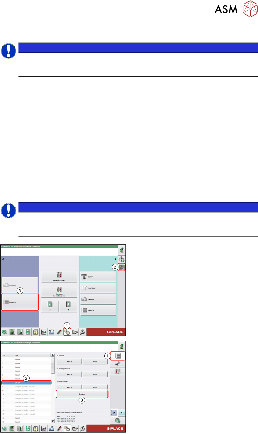
► In the station software, select the Single
functions view(1) and then the Subsys-
tems area (2).
► Select the Location (3) on which the LDU
is set up.
► Select the Feeder area (1).
► Select the LDU in the list of set up feeders
(2)
.
► Click on the Details…button (3).