TR7600 SIII_Camera_Calibration_en_v_2_0_2 - 第12页
Test Research, Inc. 6 TR7600 SI II Series User Guide – Camera Ca libration Figure 164: Choose Laser Sen sor 2 ...... .... ....... .... ....... .... ....... .... ....... .... ....... .... ...... ..... .. 79 Figure 165: Ca…

Test Research, Inc.
TR7600 SIII Series User Guide – Camera Calibration 5
Figure 123: Amplifier/Zero Shift ...................................................................................... 64
Figure 124: Top View of Laser Sensor Arrangement ..................................................... 65
Figure 125: Laser Sensor Arrangement ......................................................................... 65
Figure 126: Registries ..................................................................................................... 66
Figure 127: Laser Sensor Related Registries ................................................................ 66
Figure 128: Laser Offset ................................................................................................. 66
Figure 129: Choose Laser Sensor 0 .............................................................................. 67
Figure 130: Set Scan Info ............................................................................................... 67
Figure 131: Don’t Use These Buttons to Scan the Board .............................................. 67
Figure 132: Use this Column Circles for Calibration ...................................................... 68
Figure 133: Move the Box Close to One Column Circles .............................................. 68
Figure 134: Live .............................................................................................................. 69
Figure 135: Record the Value in the Laser Sensor0 Field ............................................. 69
Figure 136: Fill in the Value in the Registry ................................................................... 70
Figure 137: Choose Laser Sensor 1 .............................................................................. 70
Figure 138: Record the Value from the Laser Sensor1 Field ........................................ 70
Figure 139: Fill in the Value in the Registry ................................................................... 70
Figure 140: Choose Laser Sensor 2 .............................................................................. 71
Figure 141: Record the Value in the Sensor2 Field ....................................................... 71
Figure 142: Fill in the Value in the Registry ................................................................... 71
Figure 143: Left In - Right Out Board ............................................................................. 71
Figure 144: Calibration Board ......................................................................................... 72
Figure 145: Place the Sensor at Position A and Position B ........................................... 72
Figure 146: Place the Sensor at Position A and Position B ........................................... 72
Figure 147: Laser Offset ................................................................................................. 72
Figure 148: Choose Laser Sensor 0 .............................................................................. 73
Figure 149: Set Scan Info. .............................................................................................. 73
Figure 150: Don’t Use These Buttons to Scan the Board .............................................. 73
Figure 151: Position A and Position B ............................................................................ 74
Figure 152: Move the Box to Position A ......................................................................... 74
Figure 153: Record the Value in the Laser Sensor0 Field ............................................. 75
Figure 154: Laser Offset ................................................................................................. 75
Figure 155: Choose Laser Sensor 0 .............................................................................. 76
Figure 156: Set Scan Info ............................................................................................... 76
Figure 157: Don’t Use These Buttons to Scan the Board .............................................. 76
Figure 158: Position A and Position B ........................................................................... 77
Figure 159: Move the Box to Position B ......................................................................... 77
Figure 160: Record the Value in the Laser Sensor0 Field ............................................. 78
Figure 161: Calculate the Resolution Value ................................................................... 78
Figure 162: Choose Laser Sensor 1 .............................................................................. 79
Figure 163: Calculate the Resolution Value ................................................................... 79

Test Research, Inc.
6 TR7600 SIII Series User Guide – Camera Calibration
Figure 164: Choose Laser Sensor 2 .............................................................................. 79
Figure 165: Calculate the Resolution Value ................................................................... 79
Test Research, Inc.
TR7600 SIII Series User Guide – Camera Calibration 7
1 P
REPARATION
B
EFORE
C
ALIBRATION
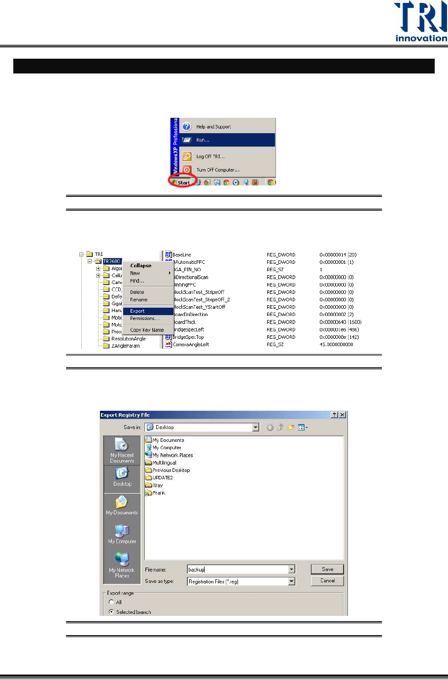
1) Back up the registry file:
a) Click [Start] [Run] Input “Regedit”.
Figure 1: Click [Start]
[Run]
b) Right-click on the TR7600 folder Select [Export].
Figure 2: Export the Backup to the Desktop
c)
Back up the registry file as "backup.reg" on the desktop.
Figure 3: Save the Registry File