TR7600 SIII_Camera_Calibration_en_v_2_0_2 - 第35页
Test Research, Inc. TR7600 SIII Ser ies User G uide – Cam era Calibr ation 29 Calibration W indow Introduction Figure 41 : Calibration W indow 1) 2D Image W indow 2) Grab I mage Control 3) Li ghting Source Control 4) M…
Test Research, Inc.
28 TR7600 SIII Series User Guide – Camera Calibration
3 2D
C
AMERA AND
L
ASER
C
ALIBRATION
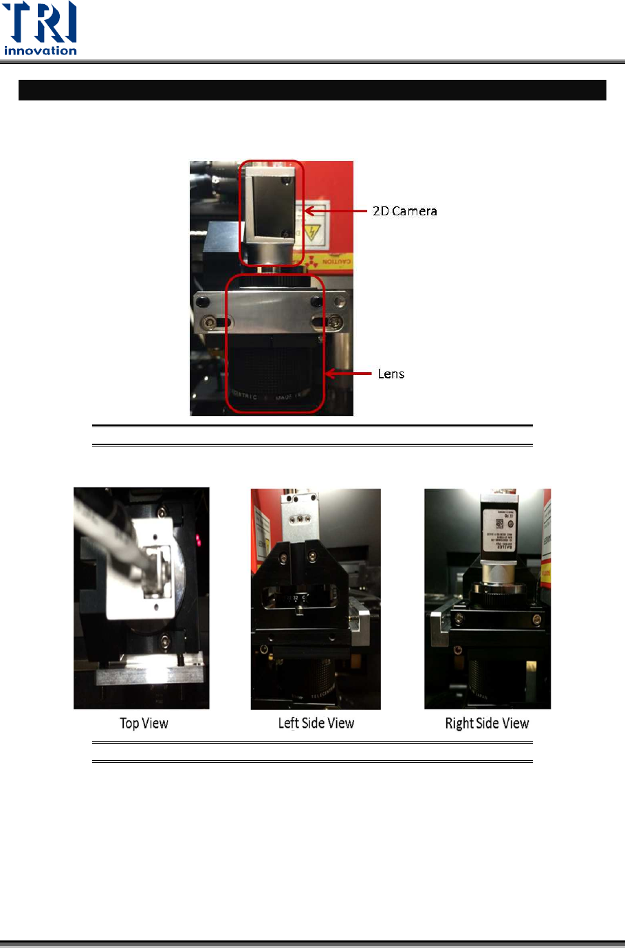
Hardware Introduction
During the calibration process, adjust 2D camera and lens positions..
Figure 39: Front View
Figure 40: Top View/ Right Side View/Left Side View
Test Research, Inc.
TR7600 SIII Series User Guide – Camera Calibration 29
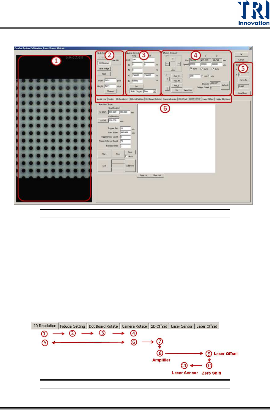
Calibration Window Introduction
Figure 41: Calibration Window
1) 2D Image Window
2) Grab Image Control
3) Lighting Source Control
4) Motion Control
5) Calibration Board Parameters
6) Calibration Flow
Calibration Procedure
Perform 2D camera calibration and laser calibration independently.
• In order to perform the calibrations, users can follow step (1)~(11) as indicated
below.
Figure 42: Calibration Procedure
Test Research, Inc.
30 TR7600 SIII Series User Guide – Camera Calibration
• If only 2D calibration to be performed, execute step (1)~(6). If the calibration
result is not good, repeat 2D Resolution and Camera Rotate steps several times
until the [OK] message appeared.
• Execute step (7)~(11) for laser calibration.
2D Camera Calibration
1. 2D Resolution: Calibrate 2D camera resolution approximately.
2. Fiducial Setting: Set up Fiducial Mark.
3. Dot Board Rotate: Rotate calibration board if necessary.
4. Camera Rotate: Rotate 2D camera if necessary.
5. 2D Resolution: Calibrate 2D camera resolution precisely.
6. Camera Rotate: Re-confirm 2D camera angle.
Laser Calibration
7. 2D Offset: Align the coordinates of X-ray tube, scanned image and 2D image.
8. Amplifier: Set up amplifier to increase the accuracy of laser detection.
9. Laser offset: Use square hole’s position for laser positioning.
10. Zero Shift: Set up zero height for all Laser Sensors and Amplifiers.
11. Laser Sensor: Input the information of Laser Sensors and Amplifiers to registries.
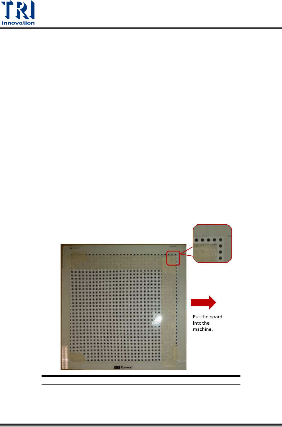
Start the Calibration
Input the calibration board into the machine manually. Put tape on the calibration board
(as shown below) by leaving one row circle and one column circle at the upper-right
boundary. Make sure that the calibration board surface is clean.
Figure 43: Calibration Board