TR7600 SIII_Camera_Calibration_en_v_2_0_2 - 第38页
Test Research, Inc. 32 TR7600 SI II Series User Guide – Camera Ca libration 3.1 2D Resolu tion This section is used to calibrate 2D camera a pproximately. 1) Click on [2D Resolution] . Figure 46: 2D Resolutio n 2) Clic…
Test Research, Inc.
TR7600 SIII Series User Guide – Camera Calibration 31
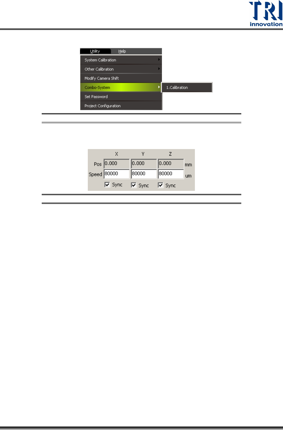
Turn on the main programclick on [Utility][Combo-System]choose [Calibration].
Figure 44: Combo System
Calibration
Make sure the [Sync X], [Sync Y], [Sync Z] functions are enabled during the calibration
process.
Figure 45: Make Sure All [Sync] Fields Are Enabled
Test Research, Inc.
32 TR7600 SIII Series User Guide – Camera Calibration
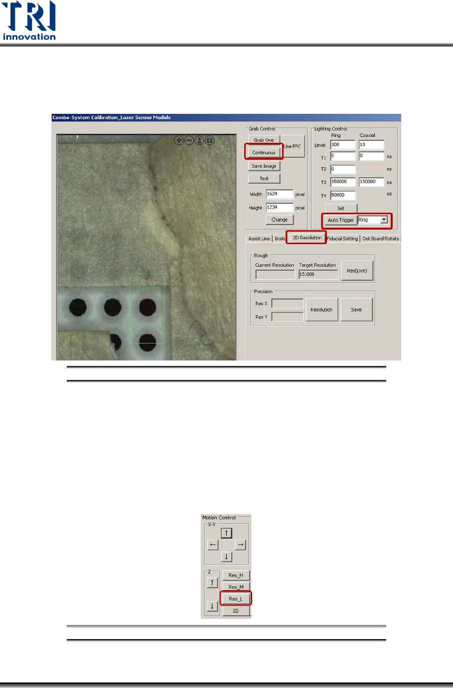
3.1 2D Resolution
This section is used to calibrate 2D camera approximately.
1) Click on [2D Resolution].
Figure 46: 2D Resolution
2) Click on [Auto trigger] and choose [Ring] in the drop down menu.
Note: It does not matter which type of laser source is choosed.
• [Ring]: Use ring type laser source. The number in the [Level] field should be set
within 0~127.
• [Coaxial]: Use coaxial type laser source.
• [MultI]: Use ring and coaxial type laser sources at the same time.
3) Click on [Continuous].
4) Click on [Res. L] to move 2D camera to a default height. By doing so, calibration time is
reduced.
Figure 47: Click [Res. L]
Test Research, Inc.
TR7600 SIII Series User Guide – Camera Calibration 33
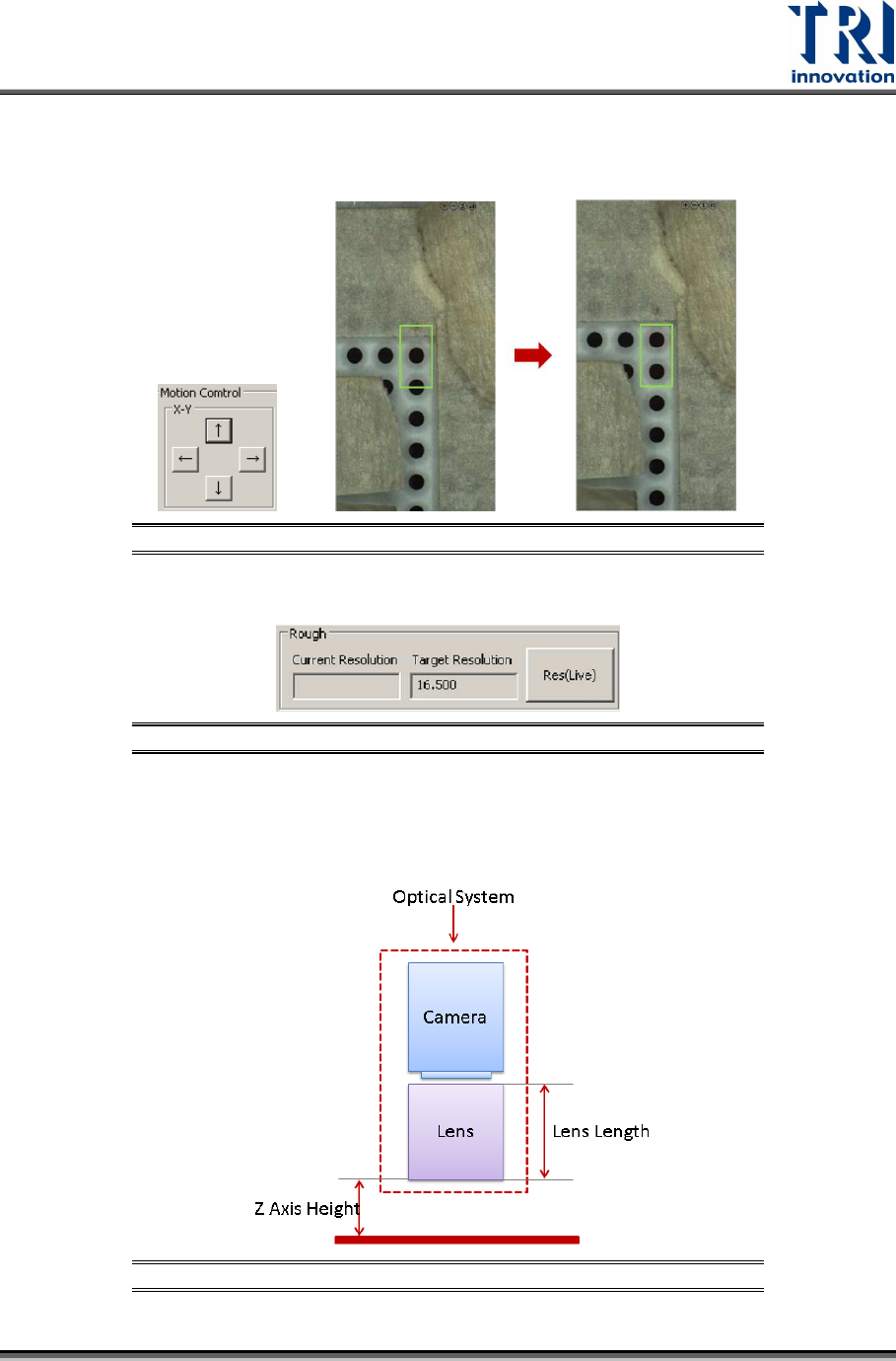
5) Use [↑], [↓], [←], or [→] buttons to move two circles situated at the uppermost right
corner to the center of the rectangle box. Another option is drag or click directly on the
left side 2D image to move these two circles to the center of rectangle box.
Figure 48: Move Two Circles to the Center of the Rectangle Box
6) Click [Res(Live)] and the main program will calculate the current resolution automatically.
Figure 49: Click [Res(Live)]
7) Before the calibration, the current resolution and target resolution may be totally different.
Adjust the lens height and Z axis height to make the difference between current
resolution and target resolution smaller than 0.1.
Figure 50: Optical System