TR7600 SIII_Camera_Calibration_en_v_2_0_2 - 第43页
Test Research, Inc. TR7600 SIII Ser ies User G uide – Cam era Calibr ation 37 3.2 Fiducial Setting Set up Fiduc ial Mark as the calibration reference point. 1) Click on [Fiducial Setting]. Figure 58: Fiducial Settin g …
Test Research, Inc.
36 TR7600 SIII Series User Guide – Camera Calibration
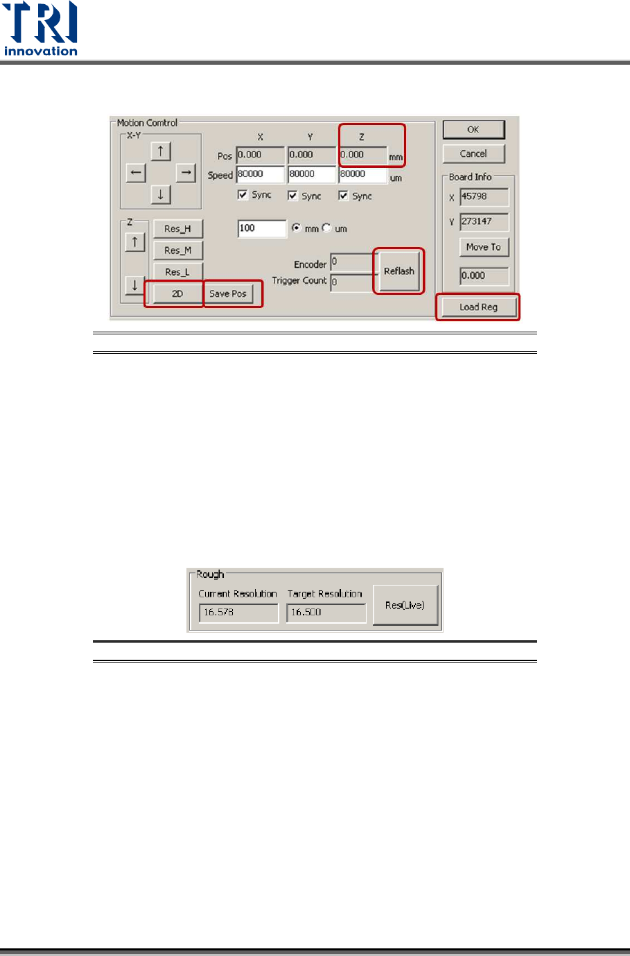
8) Click on [Save Pos] to save data to the registry.
Figure 56: Save Pos/Load Reg/Refresh/Record Z Axis Height
9) Click on [Load Reg] to load the registry in order to check if the data is saved. Do not
need to restart the main program.
10) Click on [Refresh] to update all values on the screen.
11) Record the Z axis height named as H1 in the Z position field.
12) Click on [Res_H] or [Res_M] buttons to change the current Z axis height.
13) Click on [2D] to move 2D camera to the assigned height.
14) Click on [Refresh] to update all values.
15) Check the Z axis height named as H2.
16) If H1 equals to H2, the data has been saved to the registry successfully.
17) Click on [Res(Live)].
Figure 57: Click on [Res(Live)]
18) Try different lens height and Z axis height until the difference between the current
resolution and target resolution is smaller than 0.1.
19) Fasten the screws.
Test Research, Inc.
TR7600 SIII Series User Guide – Camera Calibration 37
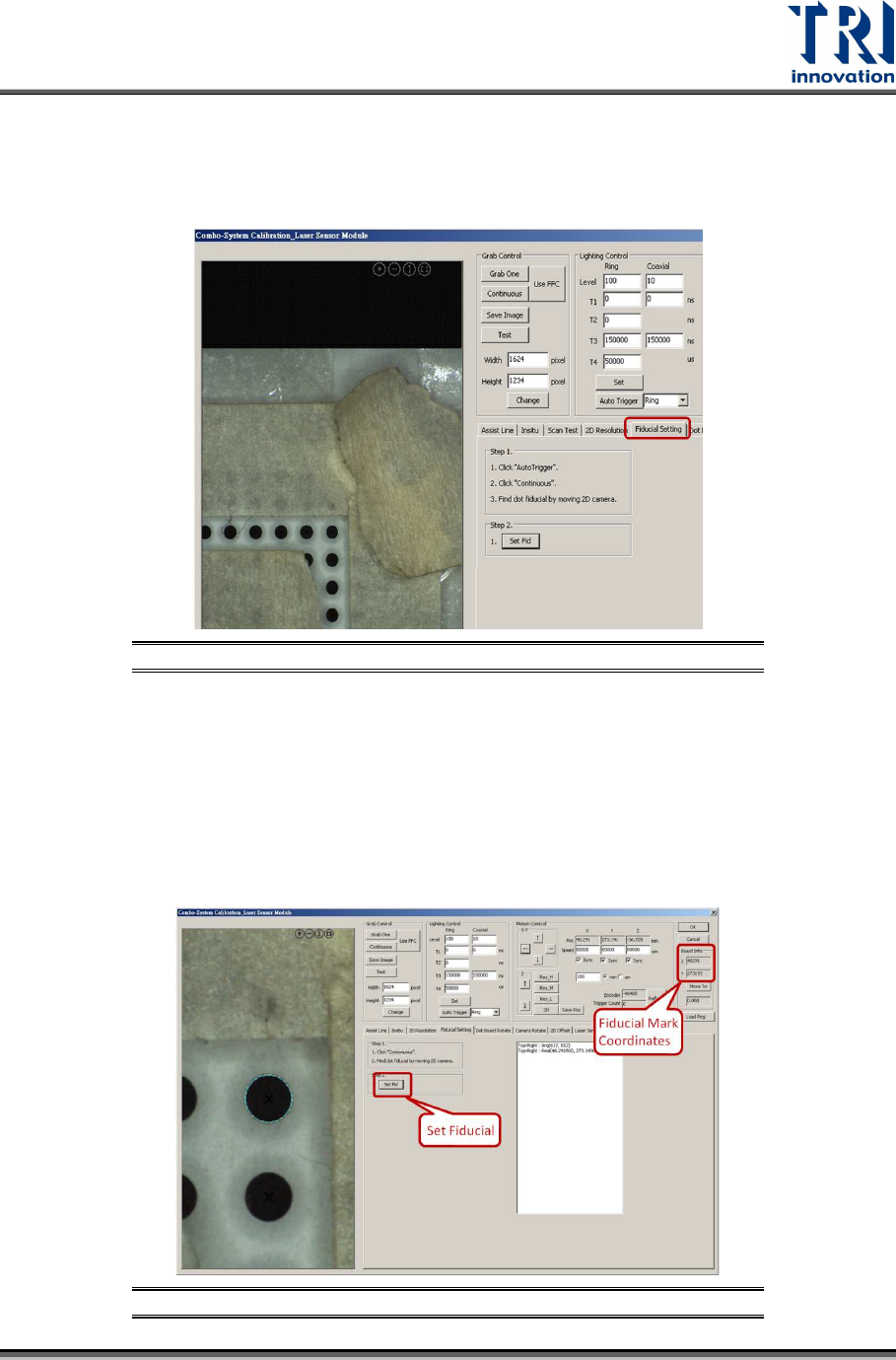
3.2 Fiducial Setting
Set up Fiducial Mark as the calibration reference point.
1) Click on [Fiducial Setting].
Figure 58: Fiducial Setting
2) Click on [Auto Trigger]. If the visible light is still on, do not need to click [Auto
Trigger].
3) Make sure the [Continuous] button is still checked.
4) Move the point located at uppermost right corner to the window center.
5) Click on [Set Fid] to set the point as the Fiducial Mark. If the setup is successful,
this point will be confined by a circle and its coordinates will be recorded in the [X]
and [Y] fields.
Figure 59: Set Up Fiducial Mark
Test Research, Inc.
38 TR7600 SIII Series User Guide – Camera Calibration
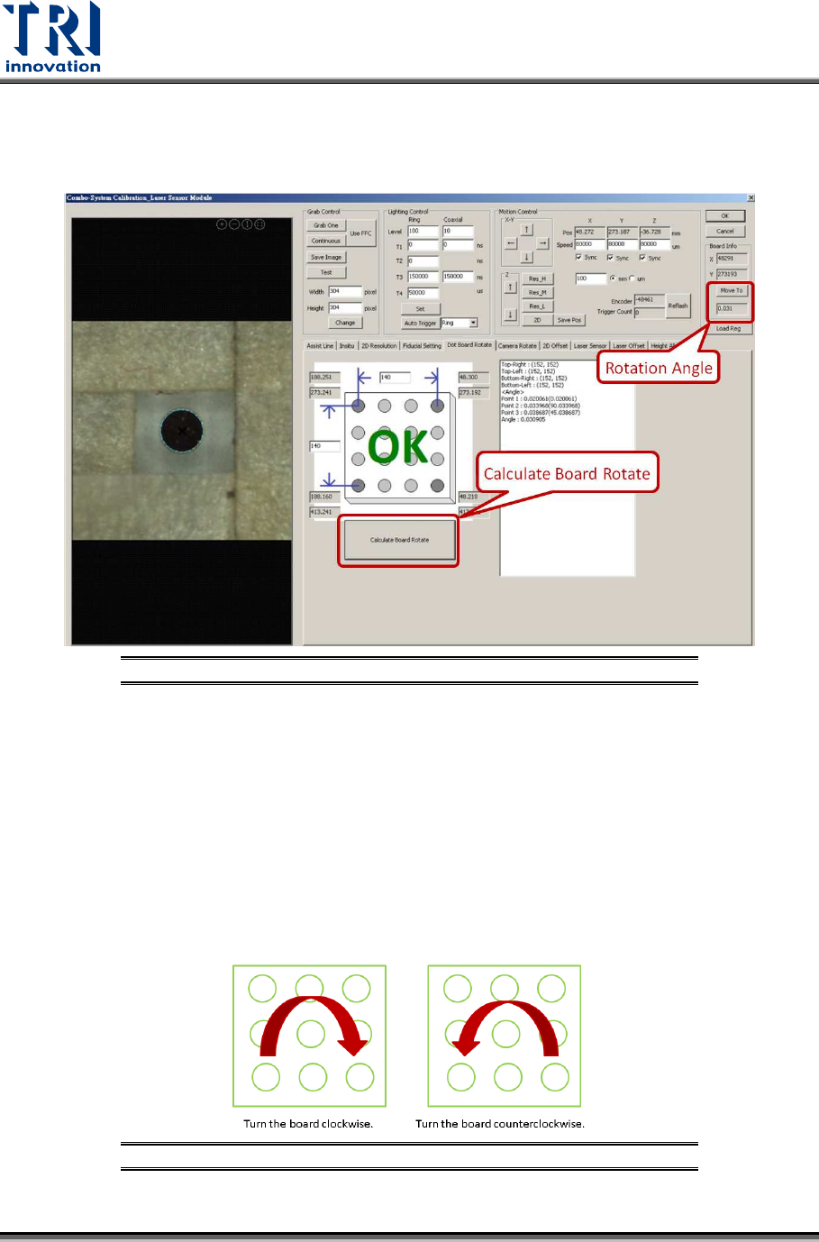
3.3 Dot Board Rotate:
1) Click on [Dot Board Rotate]
2) Click on [Calculate Board Rotate].
Figure 60: Dot Board Rotate
3) Confirm the angle in [Move To] field is within -4.5~+4.5 degrees. If yes, click on
[Camera Rotate] and move to the next step.
4) If the angle is not within -4.5~+4.5 degrees, rotate the calibration board until [OK]
message appeared.
5) From the value, users will know whether to turn the calibration board clockwise or
counterclockwise. Calibration board need to be turned manually when it is
clamped on the conveyor.
6) After the calibration board is turned, click on [Calculate Board Rotate] to re-
calculate the angle again. Repeat this step several times until [OK] message
appeared.
Figure 61: Turn the Board as Indicated