TR7600 SIII_Camera_Calibration_en_v_2_0_2 - 第44页
Test Research, Inc. 38 TR7600 SI II Series User Guide – Camera Ca libration 3.3 Dot B oard Rotate : 1) Click on [Dot Board Rotate] 2) Click on [Calculate Board Rotate] . Figure 60: Dot Board Rot ate 3) Conf irm the angle…
Test Research, Inc.
TR7600 SIII Series User Guide – Camera Calibration 37
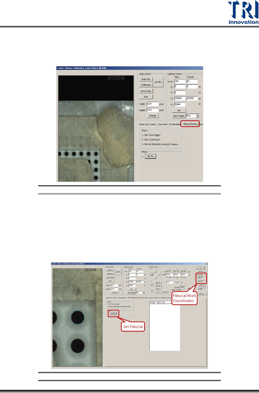
3.2 Fiducial Setting
Set up Fiducial Mark as the calibration reference point.
1) Click on [Fiducial Setting].
Figure 58: Fiducial Setting
2) Click on [Auto Trigger]. If the visible light is still on, do not need to click [Auto
Trigger].
3) Make sure the [Continuous] button is still checked.
4) Move the point located at uppermost right corner to the window center.
5) Click on [Set Fid] to set the point as the Fiducial Mark. If the setup is successful,
this point will be confined by a circle and its coordinates will be recorded in the [X]
and [Y] fields.
Figure 59: Set Up Fiducial Mark
Test Research, Inc.
38 TR7600 SIII Series User Guide – Camera Calibration
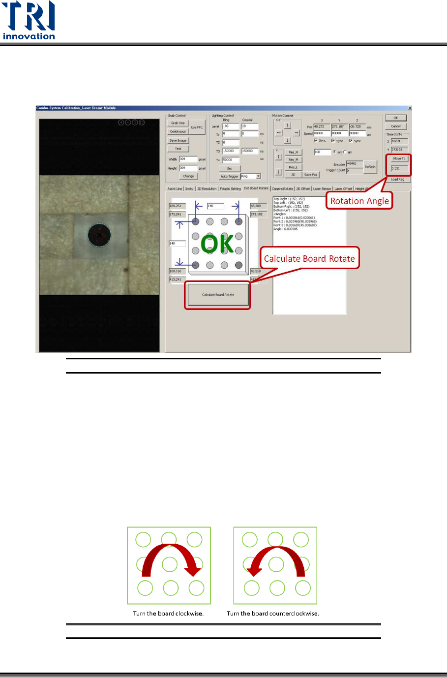
3.3 Dot Board Rotate:
1) Click on [Dot Board Rotate]
2) Click on [Calculate Board Rotate].
Figure 60: Dot Board Rotate
3) Confirm the angle in [Move To] field is within -4.5~+4.5 degrees. If yes, click on
[Camera Rotate] and move to the next step.
4) If the angle is not within -4.5~+4.5 degrees, rotate the calibration board until [OK]
message appeared.
5) From the value, users will know whether to turn the calibration board clockwise or
counterclockwise. Calibration board need to be turned manually when it is
clamped on the conveyor.
6) After the calibration board is turned, click on [Calculate Board Rotate] to re-
calculate the angle again. Repeat this step several times until [OK] message
appeared.
Figure 61: Turn the Board as Indicated
Test Research, Inc.
TR7600 SIII Series User Guide – Camera Calibration 39
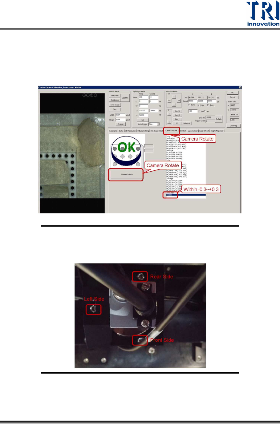
3.4 Camera Rotate:
This step is used to align the coordinates of camera to X and Y axes.
1) Click on [Camera Rotate] that is next to the [Dot Board Rotate] button.
2) Click on [Camera Rotate] that is under the [OK] message as shown below.
3) If the [OK] message appeared, click on [2D Offset] and move to the next step.
Figure 62: Camera Rotate
4) If the [OK] message does not appeared, rotate the camera. Release the screws a
little bit first. The screws’ positions are indicated as below.
Figure 63: Screws Location/Top View of 2D Camera