TR7600 SIII_Camera_Calibration_en_v_2_0_2 - 第71页
Test Research, Inc. TR7600 SIII Ser ies User G uide – Cam era Calibr ation 65 3.11 Laser Sensor W he never re-do the Zero Shi ft step, Laser Sensor step need to be re-do. There are 3 laser sensors. The arrange m ent …
Test Research, Inc.
64 TR7600 SIII Series User Guide – Camera Calibration
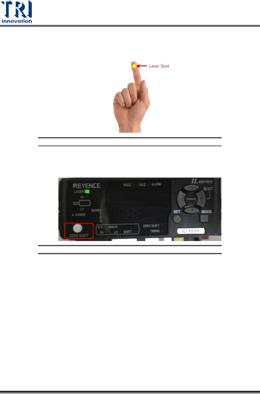
7) There are 3 amplifiers on the top of X-ray tube. Find the amplifier0 that detects
the spot of Laser Sensor0. If unable to determine which amplifier detects Laser
Sensor0, use finger to block the spot of Laser Sensor0. Meanwhile, the amplifier
that changes its value dramatically is the amplifier0.
Figure 122: Use Finger to Block the Laser Spot
8) On the amplifier0, press the [Zero Shift] button twice to set up zero height for
amplifier0.
Figure 123: Amplifier/Zero Shift
9) Choose [1] in the [Sensor Index] field.
10) Click on [Move To]. The Laser Sensor1 will move to the assigned position that
has been saved in [P1(XRay)] step.
11) Use the same way mentioned above to find out the amplifier1. Press the [Zero
Shift] button twice on the amplifier1 to set up the zero height.
12) Choose [2] in the [Sensor Index] field.
13) Click on [Move To]. The Laser Sensor2 will move to the assigned position that
has been saved in [P1(XRay)] step.
14) Find out the amplifier2. Press the [Zero Shift] button twice on the amplifier2 to set
up the zero height.
Test Research, Inc.
TR7600 SIII Series User Guide – Camera Calibration 65
3.11 Laser Sensor
Whenever re-do the Zero Shift step, Laser Sensor step need to be re-do.
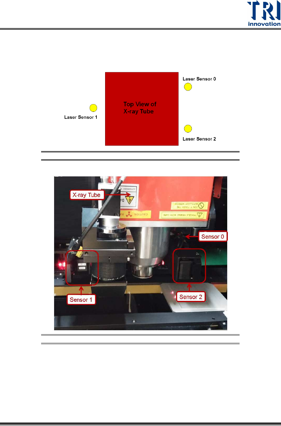
There are 3 laser sensors. The arrangement is shown as below.
Figure 124: Top View of Laser Sensor Arrangement
Figure 125: Laser Sensor Arrangement
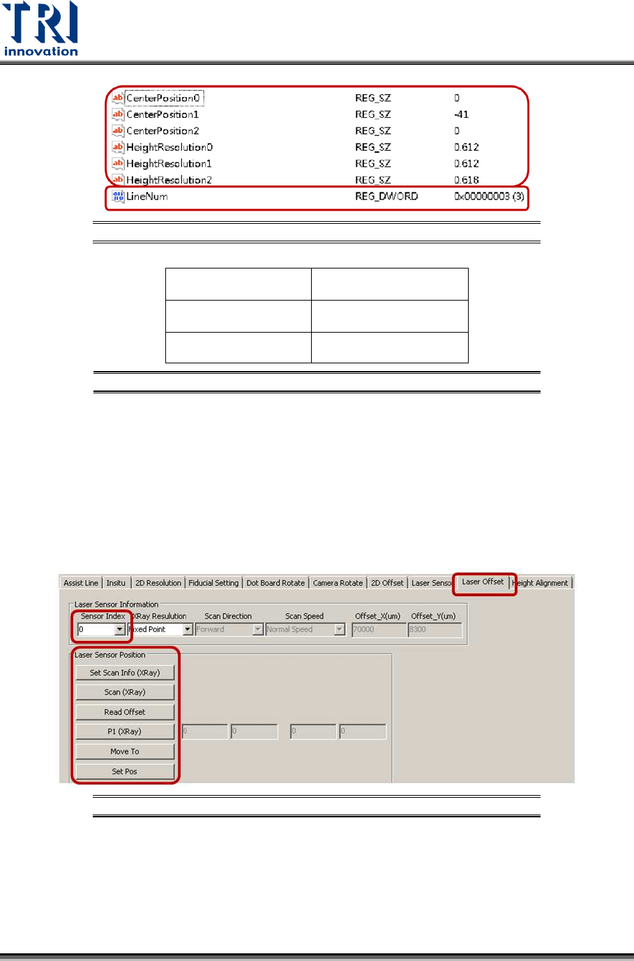
Click on [Start]input [regedit]double-click on the registry file click
[TRI\TR7600\CalibrationInfo\HeightDetect].
In the LineNum registry, the value should be 3 to imply the machine uses 3 laser
sensors.
For each Laser Sensor, find the information for Center Position registry and High
Resolution registry.
Test Research, Inc.
66 TR7600 SIII Series User Guide – Camera Calibration
Figure 126: Registries
Laser Sensor0
Center Position0
Height Resolution0
Laser Sensor1
Center Position1
Height Resolution1
Laser Sensor2
Center Position2
Height Resolution2
Figure 127: Laser Sensor Related Registries
Follow below steps to find out the information for all Center Position registries first.
During the process, move the spots of three Laser Sensors to one column of
circles. It will not be easy to check the positions of laser spots. Switch back to
[Laser Offset] page first and use [Move To] button to move laser spots next to
one column circles. Next, switch back to [Laser Sensor] page and record the
laser intensity value.
1) Click on [Laser Offset].
Figure 128: Laser Offset