TR7600 SIII_Camera_Calibration_en_v_2_0_2 - 第73页
Test Research, Inc. TR7600 SIII Ser ies User G uide – Cam era Calibr ation 67 2) Choos e [0] in the [Sensor Index] field. Figure 129: Choose L aser Senso r 0 3) Click on [Set Scan Info(XRay)] to set up the scan paramater…
Test Research, Inc.
66 TR7600 SIII Series User Guide – Camera Calibration
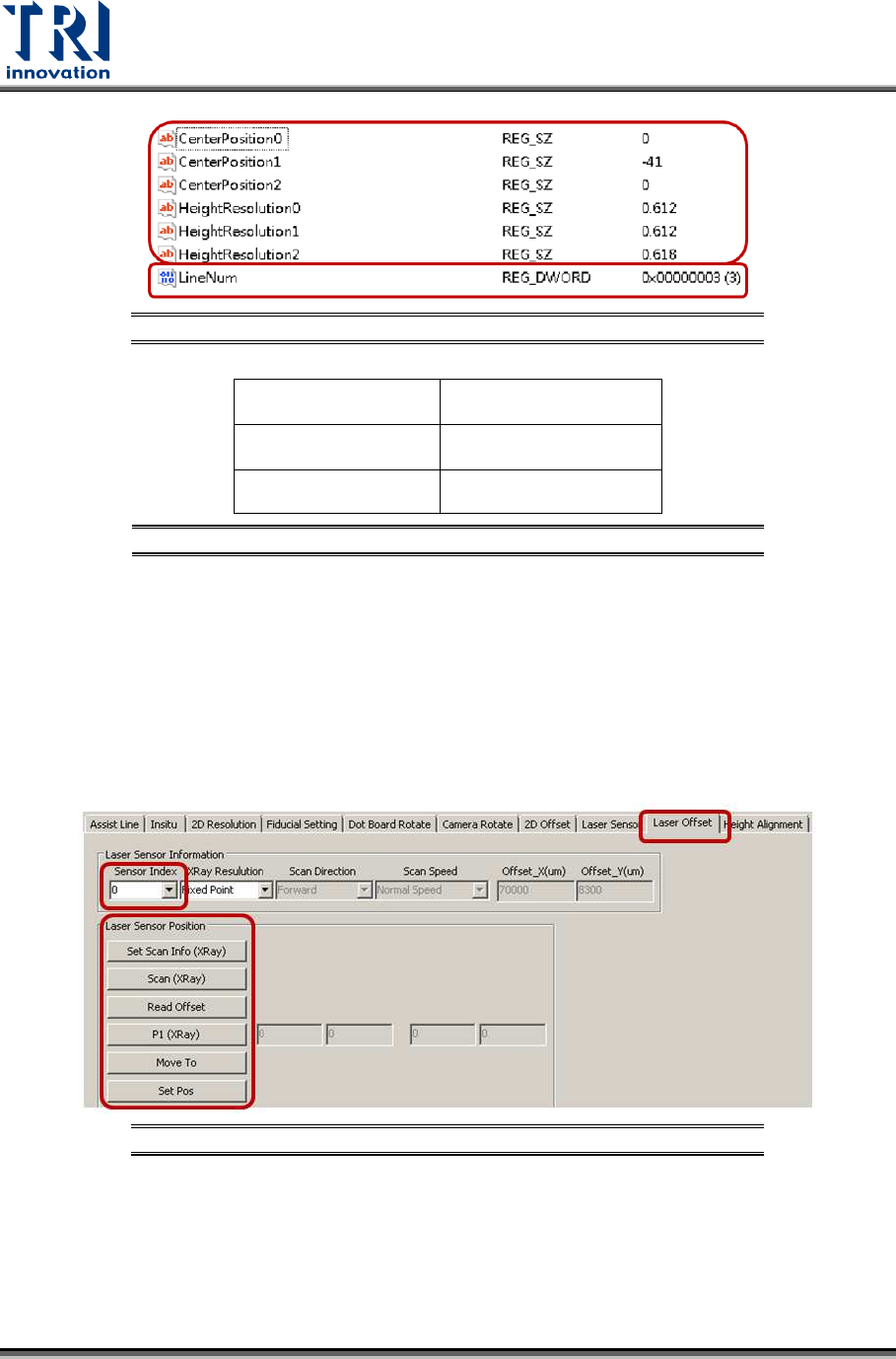
Figure 126: Registries
Laser Sensor0
Center Position0
Height Resolution0
Laser Sensor1
Center Position1
Height Resolution1
Laser Sensor2
Center Position2
Height Resolution2
Figure 127: Laser Sensor Related Registries
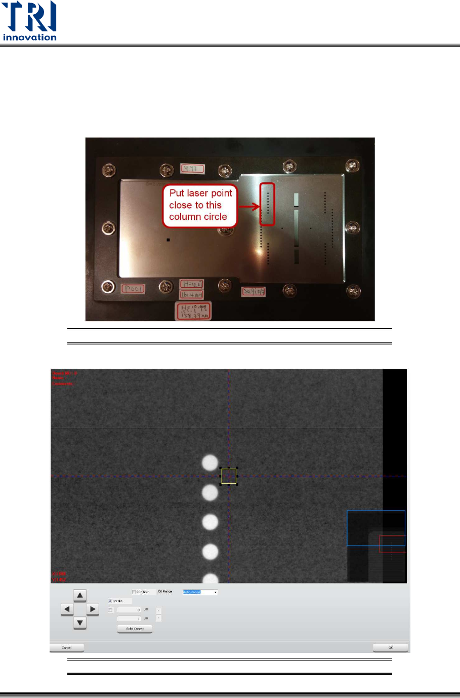
Follow below steps to find out the information for all Center Position registries first.
During the process, move the spots of three Laser Sensors to one column of
circles. It will not be easy to check the positions of laser spots. Switch back to
[Laser Offset] page first and use [Move To] button to move laser spots next to
one column circles. Next, switch back to [Laser Sensor] page and record the
laser intensity value.
1) Click on [Laser Offset].
Figure 128: Laser Offset
Test Research, Inc.
TR7600 SIII Series User Guide – Camera Calibration 67
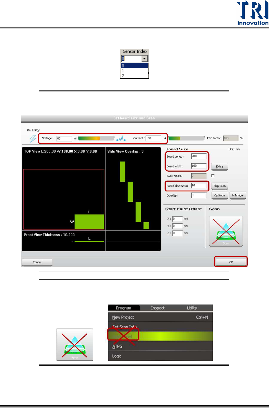
2) Choose [0] in the [Sensor Index] field.
Figure 129: Choose Laser Sensor 0
3) Click on [Set Scan Info(XRay)] to set up the scan paramaters and click on [OK].
Figure 130: Set Scan Info
4) Please don’t use the [Scan] buttons shown as below to scan the board.
Figure 131: Don’t Use These Buttons to Scan the Board
Test Research, Inc.
68 TR7600 SIII Series User Guide – Camera Calibration
5) Click on [Scan (XRay)] to scan the board and the main program will calculate the
data needed.
6) Click on [P1(XRay)].
7) Move the box to one column circles closely, but still keep the box on the metal
surface, so amplifiers can record the metal surface as zero height.
8) Click on [OK] to save the box coordinates.
Figure 132: Use this Column Circles for Calibration
Figure 133: Move the Box Close to One Column Circles