TR7600 SIII_Camera_Calibration_en_v_2_0_2 - 第77页
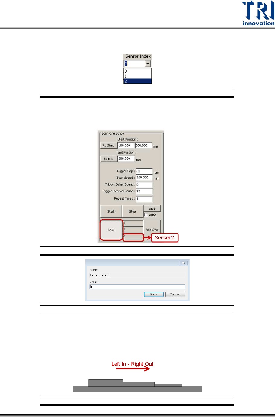
Test Research, Inc. TR7600 SIII Ser ies User G uide – Cam era Calibr ation 71 17) Repeat the s teps f rom s tep 2 to s tep 12 f or Laser S ensor 2. In step 2, r emember to choose [2] in the [Sensor Index ] drop down menu…
Test Research, Inc.
70 TR7600 SIII Series User Guide – Camera Calibration
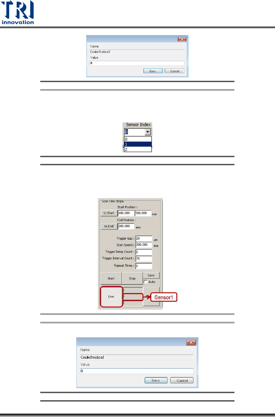
Figure 136: Fill in the Value in the Registry
15) Repeat the steps from step 2 to step 12 for Laser Sensor 1. In step 2, remember
to choose [1] in the [Sensor Index] drop down menu.
Figure 137: Choose Laser Sensor 1
16) Read the laser intensity value from the [Sensor1] field, fill it in Center Position1
registry and click [Save]. This value should be very close to 0.
Figure 138: Record the Value from the Laser Sensor1 Field
Figure 139: Fill in the Value in the Registry
Test Research, Inc.
TR7600 SIII Series User Guide – Camera Calibration 71
17) Repeat the steps from step 2 to step 12 for Laser Sensor 2. In step 2, remember
to choose [2] in the [Sensor Index] drop down menu.
Figure 140: Choose Laser Sensor 2
18) Read the laser intensity value from the [Sensor2] field, fill it in Center Position2
registry and click [Save]. This value should be very close to 0.
Figure 141: Record the Value in the Sensor2 Field
Figure 142: Fill in the Value in the Registry
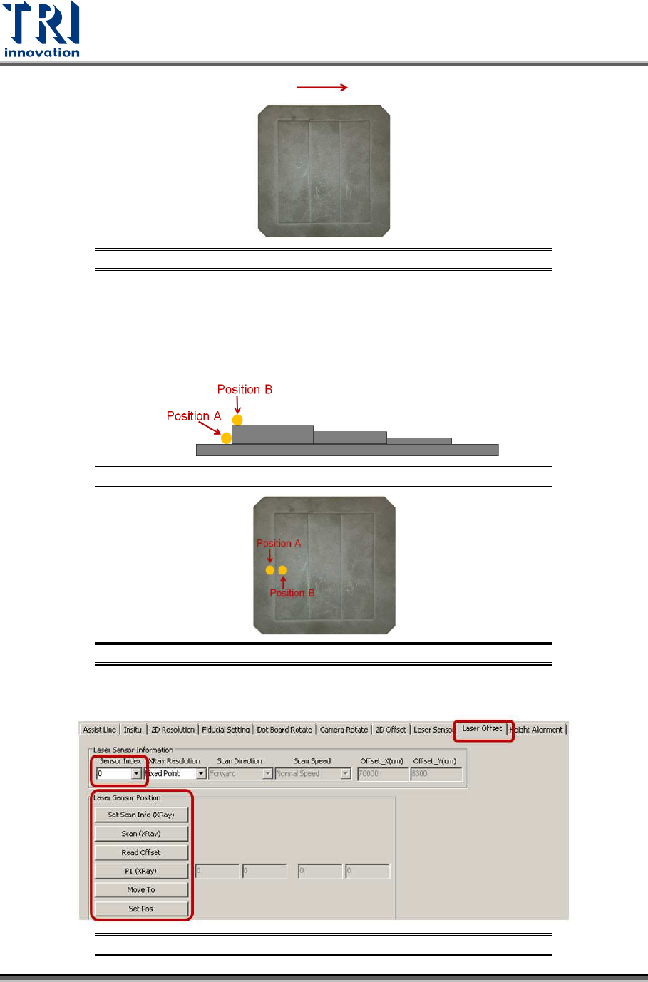
After input the laser intensity value in all Center Position registries, find the
Resolution value for Height Resolution0, Height Resolution1, and Height
Resolution2 registries. Use another calibration board for this. For left in right out
board case, put the calibration board in the direction indicated as below.
Figure 143: Left In - Right Out Board
Test Research, Inc.
72 TR7600 SIII Series User Guide – Camera Calibration
Figure 144: Calibration Board
During the process, move the spots of three Laser Sensors to position A and B
respectively. Switch back to [Laser Offset] page and use [Move To] button to
move Laser Sensors to the position A and B, and then switch back to [Laser
Sensor] page to record its laser intensity value. Follow the steps as below:
Figure 145: Place the Sensor at Position A and Position B
Figure 146: Place the Sensor at Position A and Position B
1) Click on [Laser Offset].
Figure 147: Laser Offset