TR7600 SIII_Camera_Calibration_en_v_2_0_2 - 第79页
Test Research, Inc. TR7600 SIII Ser ies User G uide – Cam era Calibr ation 73 2) Choos e [0] in the [Sensor Index] field. Figure 148: Choose L aser Senso r 0 3) Click on [Set Scan Info(XRay)] to set up the scan paramater…
Test Research, Inc.
72 TR7600 SIII Series User Guide – Camera Calibration
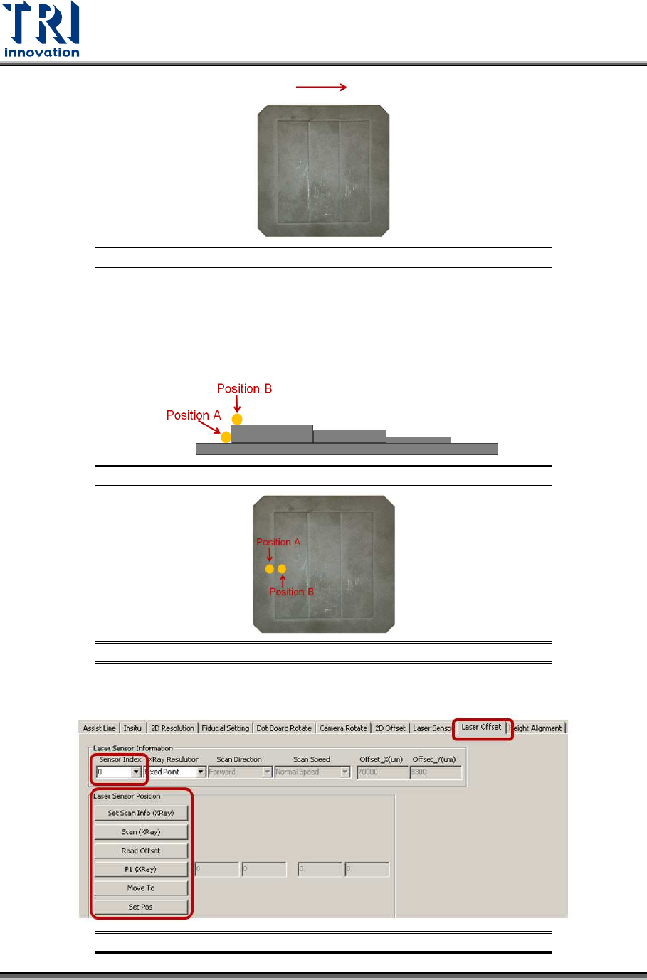
Figure 144: Calibration Board
During the process, move the spots of three Laser Sensors to position A and B
respectively. Switch back to [Laser Offset] page and use [Move To] button to
move Laser Sensors to the position A and B, and then switch back to [Laser
Sensor] page to record its laser intensity value. Follow the steps as below:
Figure 145: Place the Sensor at Position A and Position B
Figure 146: Place the Sensor at Position A and Position B
1) Click on [Laser Offset].
Figure 147: Laser Offset
Test Research, Inc.
TR7600 SIII Series User Guide – Camera Calibration 73
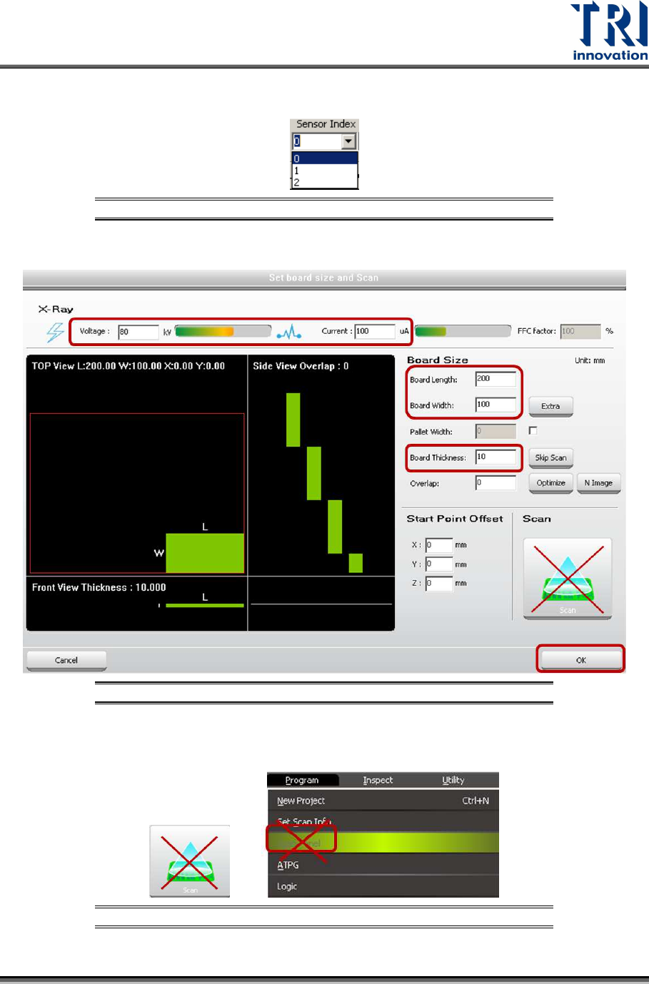
2) Choose [0] in the [Sensor Index] field.
Figure 148: Choose Laser Sensor 0
3) Click on [Set Scan Info(XRay)] to set up the scan paramaters and click on [OK].
Figure 149: Set Scan Info.
4) Do not use the [Scan] buttons shown as below to scan the board.
Figure 150: Don’t Use These Buttons to Scan the Board
Test Research, Inc.
74 TR7600 SIII Series User Guide – Camera Calibration
5) Click on [Scan (XRay)] to scan the board.
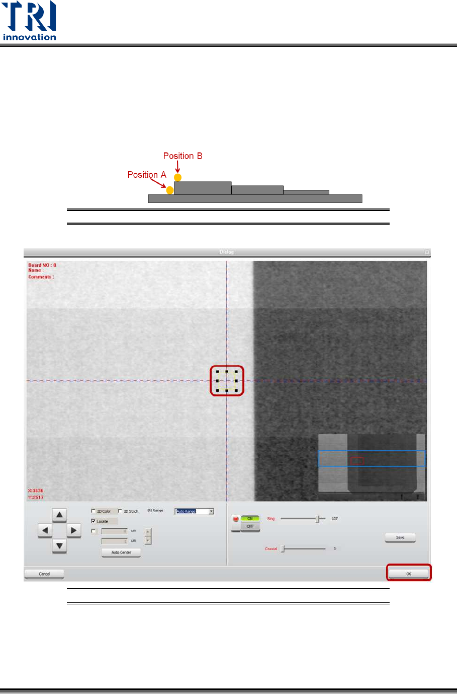
6) Click on [P1(XRay)].
7) Move the box to position A that is on the board top surface. Do not put the box
too close to the fault, or the laser point may be moved to the fault that will result in
a wrong height calculation. However, the closer position A and position B, the
higher the accuracy.
Figure 151: Position A and Position B
Figure 152: Move the Box to Position A
8) Click on [OK] to save position A coordinates.
9) Click on [Move To] and Laser Sensor0 will move to the assigned position.
10) Click on [Laser Sensor].
11) Click on [Live] to read the laser intensity value.