CP-842E-842ME System Reference-SYS-CP842-10E.pdf - 第52页
Machine System >> Basic Operation 4-16 SYS-CP842-1.0E 3 At the “Holder” section, select which of the nozzles positions (1 to 6) will be checked. Select [A ll] to choose all six holders a s a batch. 4 T o specify th…
Machine System >> Basic Operation
SYS-CP842-1.0E 4-15
4.1.5 Nozzle Related Functions
Performing a Nozzle Check
A nozzle check is performed to determine the condition of the nozzles on the placing
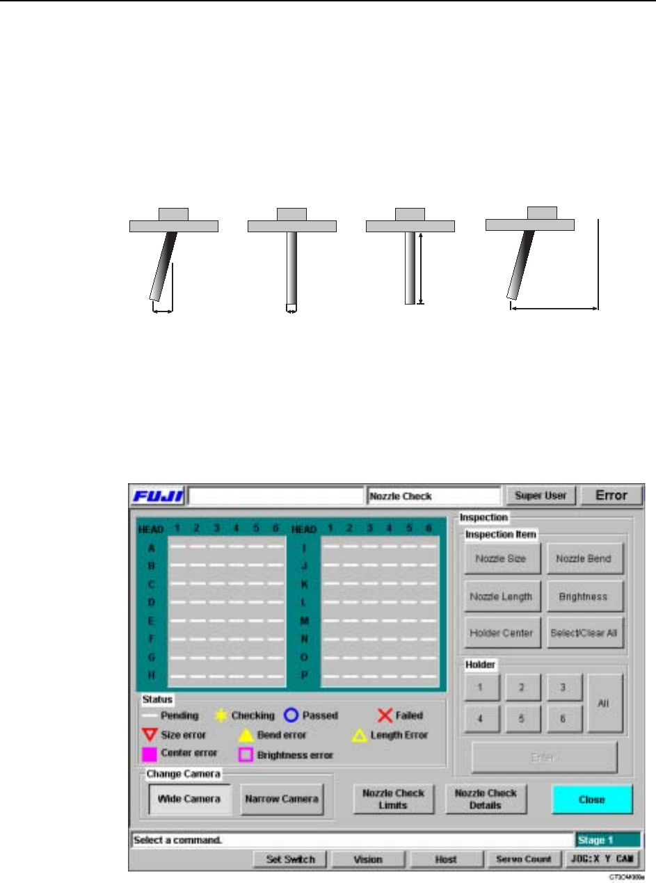
heads. The following four types of nozzle check are available, nozzle bend check, noz-
zle diameter check, nozzle length check, and the nozzle holder center check.
Procedure
1 At the [Main] window, select [Nozzle Check]. The [Nozzle Check] screen dis-
plays.
2 From the “Inspection Item” section, select which of the nozzle checks you wish
to carry out. Select [Select All] to choose all tests as a batch.
Bend Diameter Length
Holder center
End of
nozzle
Inspection
origin
C73OM001a

Machine System >> Basic Operation
4-16
SYS-CP842-1.0E
3 At the “Holder” section, select which of the nozzles positions (1 to 6) will be
checked. Select [All] to choose all six holders as a batch.
4 To specify the tolerance limits for the nozzle check, press [Nozzle Check Limits].
5 At “Change Display”, select between displaying results for the narrow camera,
or the wide camera.
6 When your settings are complete, press [Enter] to enable the START button.
Press the START button to execute the nozzle check.
When the START button is pressed, the machine begins the specified nozzle checks.
The progress of the check is shown at the green table in the [Nozzle Check] screen. A
key of the symbols is below the results table. When the test is complete, you will be
able to see which nozzles can be used, and which nozzles need to be replaced.
Note: Nozzle replacement information is in your Mechanical Reference.
To view the statics of the nozzles gathered by the machine during the nozzle check,
press [Nozzle Check Details].
Note: Only the nozzle length inspection is performed for frontlight type black nozzles.
Machine System >> Basic Operation
SYS-CP842-1.0E 4-17
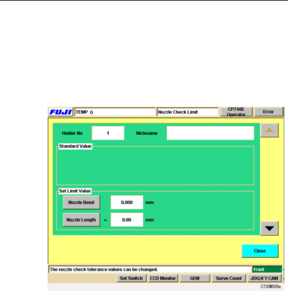
Specifying Nozzle Tolerance Values at the Machine
You can set the tolerances values for the various nozzle checks at the [Nozzle Check
Limits] screen. The settings made at this screen are used to determine whether noz-
zles are acceptable for production or not.
Procedure
1 At the [Main] screen, press [Nozzle Check]. The [Nozzle Check] screen displays.
2 From the [Nozzle Check] screen, press [Nozzle Check Limits]. The following
screen displays.
3 The screen for holder 1 tolerance values displays first. Use the up and down
arrows on the right to move between the nozzle holders.
4 In the “Set Limit Value” section, select the tolerance to be set. When you select
a command, the numeric keypad displays. Input the tolerance limit (the input
range displays at the numeric keypad), and press [OK] to enter the setting.
5 When your settings are complete, press [Close] to return to the [Nozzle Check]
screen.