CP-842E-842ME System Reference-SYS-CP842-10E.pdf - 第59页
Machine System >> Basic Operation SYS-CP842-1.0E 4-23 Performing a Manual Device Check Before operation ca n be commenced it is fi rst necessary to inform the machine that feeders have been correctly po si tioned i…
Machine System >> Basic Operation
4-22
SYS-CP842-1.0E
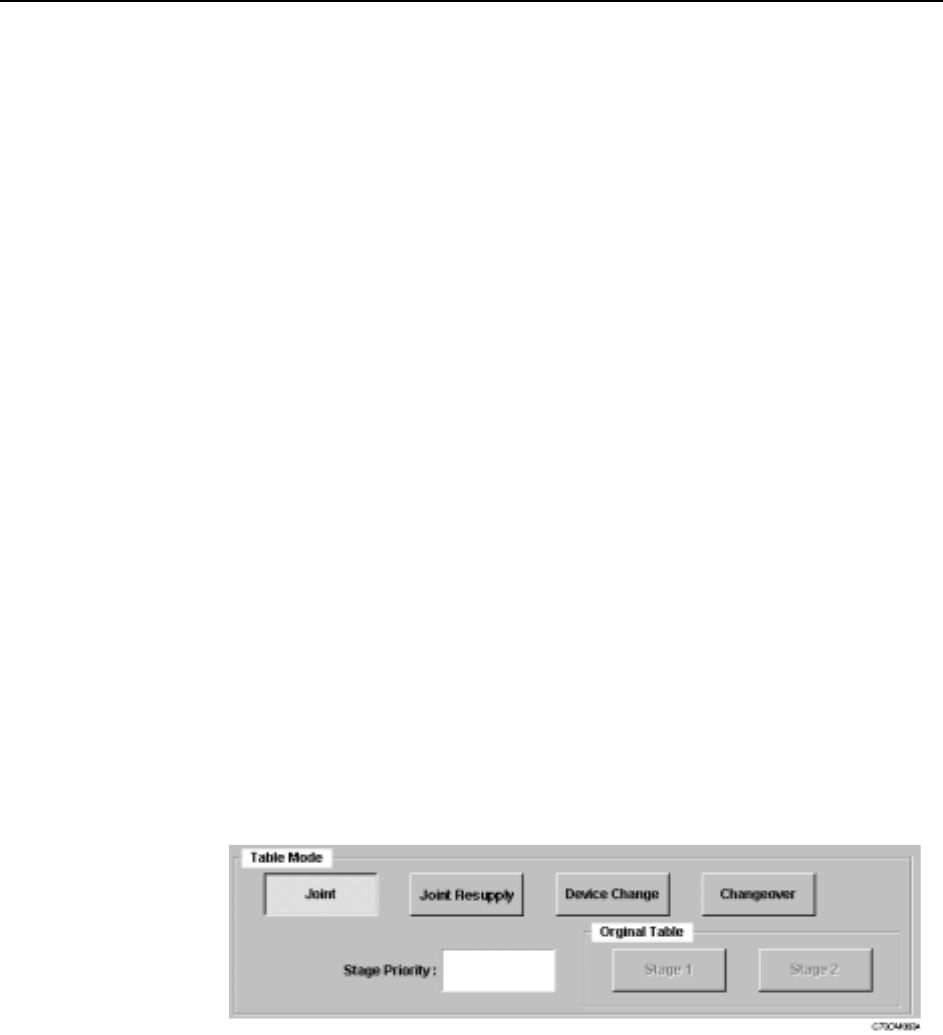
Setting the Device Table Mode
There are four modes of operation for the device tables (feeder pallets); Joint, Joint
Resupply, Device Change and Changeover.
Joint: Joint mode is suitable for supplying a wide range of parts during
assembly. Both feeder pallets are used during production, and as a
result, up to 140 part types can be loaded on the CP-842E, and up to
80 on the CP-842ME. In this mode, both tables enter the produc-
tion area and move to the pick-up position as required.
Joint Resupply: This mode is ideal for use when the device tables are changed fairly
infrequently. Joint Resupply mode is similar to Joint mode, except
only one device table is in the production area for the majority of
the time. The follow-up table (i.e., the table which is currently idle)
remains at its retract position and does not move into the produc-
tion area until just before it is needed.
Device Change: This mode is suitable for use during mass production with a fairly
small range of parts (up to CP-842E: 70/ CP-842ME: 40 part types
on each device table). Users can create two identical feeders sets
which automatically switch places when a recovery limit on the
table currently being used is reached. The device table for which
the recovery limit was reached moves to the resupply position.
Changeover: This mode is used to reduce changeover time during small lot pro-
duction. While the current table is supplying parts for the current
assembly, the spare table can be loaded with parts for the next job.
Procedure
1 At the [Main] screen, press [Operation] to display the [Operation] screen.
2 Under Table Mode, select from [Joint], [Joint Resupply], [Device Change] or
[Changeover].
3 Press [Close] to enter the settings and return to the [Main] screen.
Machine System >> Basic Operation
SYS-CP842-1.0E 4-23
Performing a Manual Device Check
Before operation can be commenced it is first necessary to inform the machine that
feeders have been correctly positioned in each of the slots that are used in the produc-
tion program. This is performed by carrying out a device check. A device check can be
performed manually or automatically, these procedures are detailed below.
Procedure
1 Press [Device Check] at the [Main] screen. The [Device Check] screen displays.
The [Device Check] screen shows a color coded box for each of the slots on each
device pallet. An explanation of the color coding system is given on the screen
itself. As can be seen, the Parts set status is shown in green, and all the slots/
feeders used in the production program must display in green before production
can commence.
2 Check the status of each feeder on the device table and press each once slot to
change the color to green.
It is also possible to use the [Select All] button to change the status of all slots
(other than those not used or not set) to green.
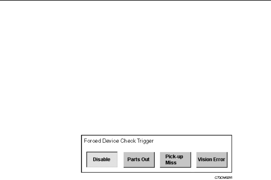
Specifying an Automatic Device Check
Each time the production program is changed or a feeder is replaced, it is possible to
make a setting to display the [Device Check] screen automatically. The user specifies
the conditions that will display [Device Check] screen at the start of automatic opera-
tion, and is notified only when an error is detected that matches the settings.
Machine System >> Basic Operation
4-24
SYS-CP842-1.0E
Procedure
1 Press [Maintenance] at the [Main] screen, and then press [Configuration] -
[Basic]. Four buttons are displayed in the Forced Device Check Trigger section.
The followings are explanations of each button.
None Automatic operation can be entered even when a device check has
not been performed.
Parts Out The [Device Check] screen displays automatically if a parts out
error is detected.
Pick-up Miss The [Device Check] screen displays automatically if a pick-up or
parts out error is detected.
Vision Error The [Device Check] screen displays automatically if a pick-up error,
inspection error, or parts out error is detected.
2 Under Forced Device Check Trigger, select the event which will invoke an auto-
matic device check.
3 Press [Close] to enter the settings and return to the [Basic Configuration]
screen.
Specifying the Next Device Trigger
Next devices provide a backup for parts supply, allowing the machine to switch to a
fresh feeder loaded with the same parts, when parts run out. The settings for a next
device loop (starting and ending at one feeder), are made in the production program.
Refer to your host system documentation for details of how to specify a next device
loop. The type of event during assembly which causes the machine to switch from one
feeder to the next can be set at the machine. The following settings are available.
Part Data The trigger setting in part data is used.
Refer to your host system documentation for details of how to make
this setting.
Parts Out The machine switches to the next device when parts out is detected.
Pick-up Miss The machine switches to the next device if a pick-up or parts out
error is detected.
Vision Error The machine switches to the next device if a pick-up error, inspec-
tion error, or parts out error is detected.
The above setting is also applied to the device change mode when switching from the
original table to the spare table.
Procedure
1 Press [Maintenance] at the [Main] screen, and then press [Configuration] -
[Basic Configuration].