CP-842E-842ME System Reference-SYS-CP842-10E.pdf - 第78页
Machine System >> Basic Operation 4-42 SYS-CP842-1.0E Camera Monitor Settings 1 Select [Maintenance] [Confi guration] [V ision Monitor] from the [Main] screen. 2 Select from [All], [4 Division], [9 Divisi on] or [1…
Machine System >> Basic Operation
SYS-CP842-1.0E 4-41
4.1.15Vision System
Displaying the Vision Monitor
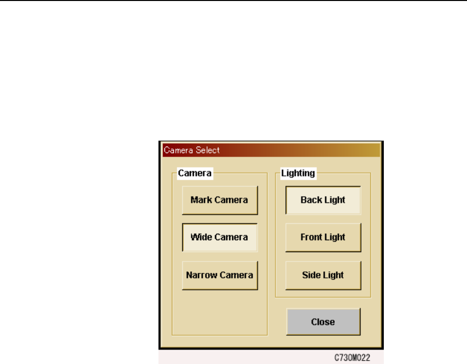
The touch screen has a built in vision monitor. Users can display the Vision Monitor
and select between the [Mark Camera], [Wide Camera] and [Narrow Camera] for the
acquired images displayed, by pressing [Vision] in the command bar. Press [Close] at
this screen to clear the Vision Monitor.
Note: During automatic operation, it is not possible to display the vision processing monitor in order
to view part images. Be sure to close the vision processing monitor before beginning auto-
matic operation.
Machine System >> Basic Operation
4-42
SYS-CP842-1.0E
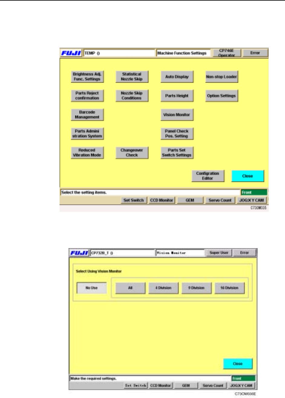
Camera Monitor Settings
1 Select [Maintenance] [Configuration] [Vision Monitor] from the [Main] screen.
2 Select from [All], [4 Division], [9 Division] or [16 Division] for the display mode
at the external vision monitor.
Machine System >> Basic Operation
SYS-CP842-1.0E 4-43
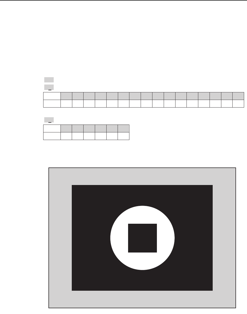
Display
Display is carried out during automatic operation, nozzle checks and PAM measure-
ments. Appended information for the current display is shown at the bottom left, if a
cycle or emergency stop occurs .
Note: This is not a realtime display during operation.
Description of the Appended Information
Display when [ ALL ] is selected
Display
Head
0 1 2 3 4 5 6 7 8 9 10 11 12 13 14 15
ABCDEFGH I JKLMNO
P
Display
Holder
012345
123456
.
>>
: Indicates the image is the last processed image acquired.
H8
: Indicates the image is of I-head.
N2
: Indicates the image is of holder 3.
T010E
>>
H8 N2
CP7S2023E