X-Series-Maintenance-Manual(1).pdf - 第15页
Introduction Calculation of Maintenance Intervals Releas e Histo ry Maintenance Manual SIPLACE X Series 15 Release History 1.4 Release History Abbreviat ions 1.5 Abbreviations Release Changes 06/2010 Revision 02/2011 Rev…
Introduction
Maintenance Notes Calculation of Maintenance Intervals
14 Maintenance Manual SIPLACE X Series
Calculat ion of Ma intenanc e Interval s
1.3.2 Calculation of Maintenance Intervals
The SIPLACE maintenance intervals are time-based and set according to the following conditions:
▪ Shift model: eight hours per shift, three shifts per day, five days a week and 50 weeks a year.
▪ Real placement performance in accordance with machine specifications
▪ Environmental and production conditions: see document "Conditions at Installation Site"
See also
4.1 Maintenance Intervals for Minor Maintenance [ ➙ 29]
5.1 Maintenance Intervals for Major Maintenance [ ➙ 63]
Adjusting the Maintenance Intervals to Actual Production Conditions
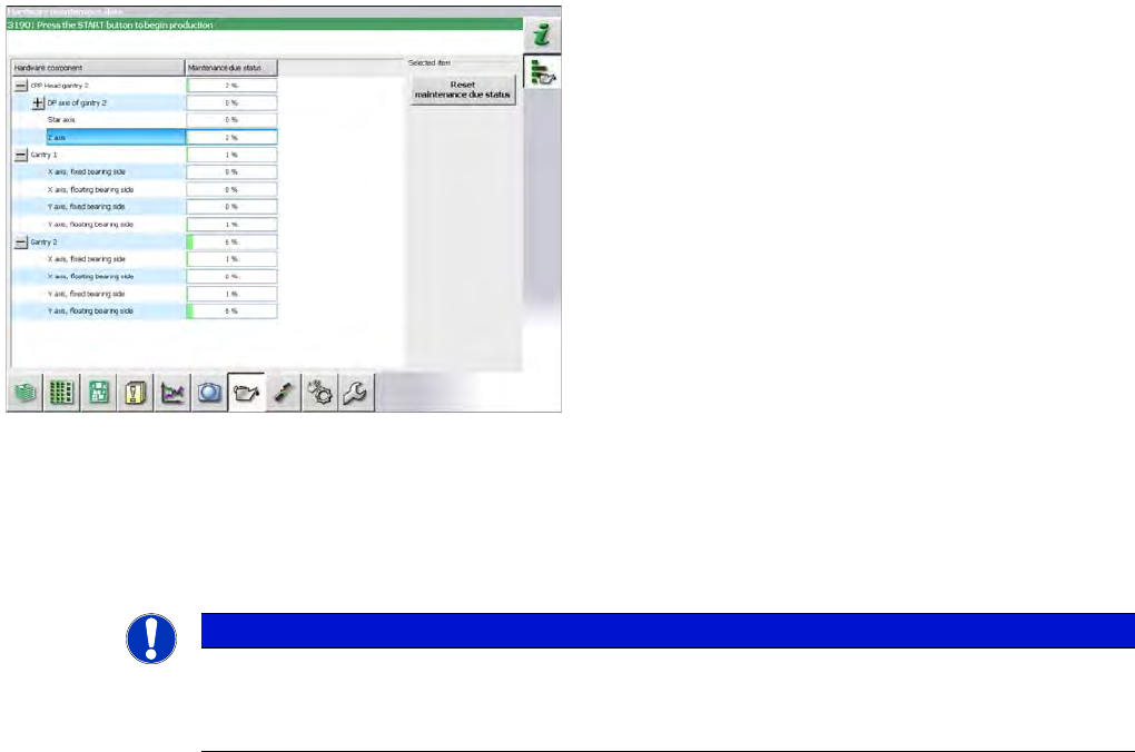
1.3.2.1 Adjusting the Maintenance Intervals to Actual Production Conditions
The maintenance status is calculated from the placement cycles, temperature and operating hours. The
status is shown as a progress bar (0 – 100 %).
Placement cycles for maintenance intervals:
▪ CPP head: 40 mill. placed components
▪ C&P20(A) head: 37.5 mill. placed components
Some customers want to adjust maintenance intervals to
their actual environment and production conditions. A
maintenance monitor can also be accessed in the station
software for some assemblies (from SW703.02).
The maintenance monitor is available for the following
assemblies:
▪ CPP head (from SW703.02)
▪ C&P20(A) head (from SW704.xx)
▪ X and Y axis (from SW703.02, SX1/SX2/DX1/DX2
only)
NOTICE
Maintenance counter
► After maintenance has been completed, the maintenance counter needs to be manually
reset for the assembly concerned.

Introduction
Calculation of Maintenance Intervals Release History
Maintenance Manual SIPLACE X Series 15
Release History
1.4 Release History
Abbreviations
1.5 Abbreviations
Release Changes
06/2010 Revision
02/2011 Revision
Abbreviations Description
PA Placement area
CO Component
COT Changeover table
COT-i Changeover table insert
C&P Collect&Place
C&P12, CP12 Collect&Place head with 12 segments
C&P20, CP20 Collect&Place head with 20 segments
C&P6, CP6 Collect&Place head with 6 segments
CPP Collect&Pick&Place head
CPx Collective term for CPP, CP20, CP12 and/or CP6
ESD Electrostatic sensitive device
EMC Electromagnetic compatibility
PCB Board
P&P, PP Pick&Place
SC Station computer
TH Twin head
VS Vision system
Introduction
Abbreviations Calculation of Maintenance Intervals
16 Maintenance Manual SIPLACE X Series