X-Series-Maintenance-Manual(1).pdf - 第67页
Major Maintenance Consumables, Spare and Wear Parts , Tools Maintenance Tasks for B ase Machin e Maintenance Manual SIPLACE X Series 67 Mainten ance Task s for Base Machi ne 5.2 Maintenance Tasks for Base Machine Consuma…

Major Maintenance
Maintenance Intervals for Major Maintenance
66 Maintenance Manual SIPLACE X Series
* see also maintenance display
See also
1.3.2 Calculation of Maintenance Intervals [ ➙ 14]
Vacuum generator:
▪ Installation/removal
▪ Clean the Venturi nozzles
▪ Blow air through Venturi nozzles
▪ Clean and grease the O-rings
▪ Clean and blow through the vacuum
generator block.
▪ Silencer: remove
▪ Silencer: clean holes to the Venturi
nozzles
▪ Silencer: check for dirt
▪ Silencer: check the plastic fixtures
6/6 X
Component sensor
▪ Clean the component sensor
1/1 X
Installation and removal of the head front
section
6/6 X
Calibrate and measure 20/25 X
Maintenance task Duration
[min]
CP6/12
Each
week
Every 3
months
Every 6
months
Every 12
months
Major Maintenance
Consumables, Spare and Wear Parts, Tools Maintenance Tasks for Base Machine
Maintenance Manual SIPLACE X Series 67
Mainten ance Task s for Base Machi ne
5.2 Maintenance Tasks for Base Machine
Consumables, Spare and Wear Parts, Tools
5.2.1 Consumables, Spare and Wear Parts, Tools
▪ If required, gas pressure shock absorber 560 N (for cover above 2 gantries) [03036763-xx] or gas
pressure shock absorber 510 N (for cover above 1 gantry) [03039170
-
xx]
▪ ESD wristband [00320279-xx]
▪ Set of Allen wrenches
▪ If required, cover switch [03020409-xx]
Preparatory Steps
5.2.2 Preparatory Steps
► There must be no PCBs on the PCB conveyor for the following jobs.
► Switch off the machine, disconnect it from the power supply and secure it to prevent unauthorized
reactivation. Observe the instructions in section "1.2 Preparatory Work..." [ ➙ 11].
Performing Maintenance Tasks
5.2.3 Performing Maintenance Tasks
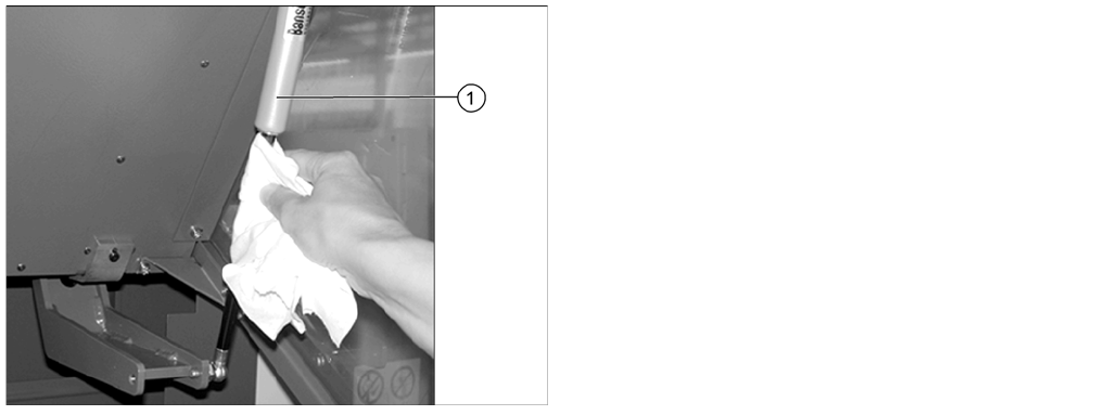
Cleaning the Gas Pressur e Shock A bsorbers on the P rotective Covers
5.2.3.1 Cleaning the Gas Pressure Shock Absorbers on the Protective Covers
► Open the protective covers.
► Wipe the sliding surfaces of the gas pressure shock
absorbers (1) clean with a lint-free cloth.
► There should be no oil visible on the pistons:
otherwise replace the gas pressure shock absorbers.
For removal and installation details, read the service
manual for the respective machine.
► Close the machine safety covers.
Major Maintenance
Maintenance Tasks for Base Machine Performing Maintenance Tasks
68 Maintenance Manual SIPLACE X Series
Check/re place the gas pres sure shock absor bers on the protec tive covers
5.2.3.2 Check/replace the gas pressure shock absorbers on the protective covers
Checking the Safety Features
5.2.3.3 Checking the Safety Features
► Make sure that the placement system is switched on and the operating system has started up.
► Make sure that "Control on" is set on the placement machine. You can tell this from the main fault
indicator.
► Press the Start button.
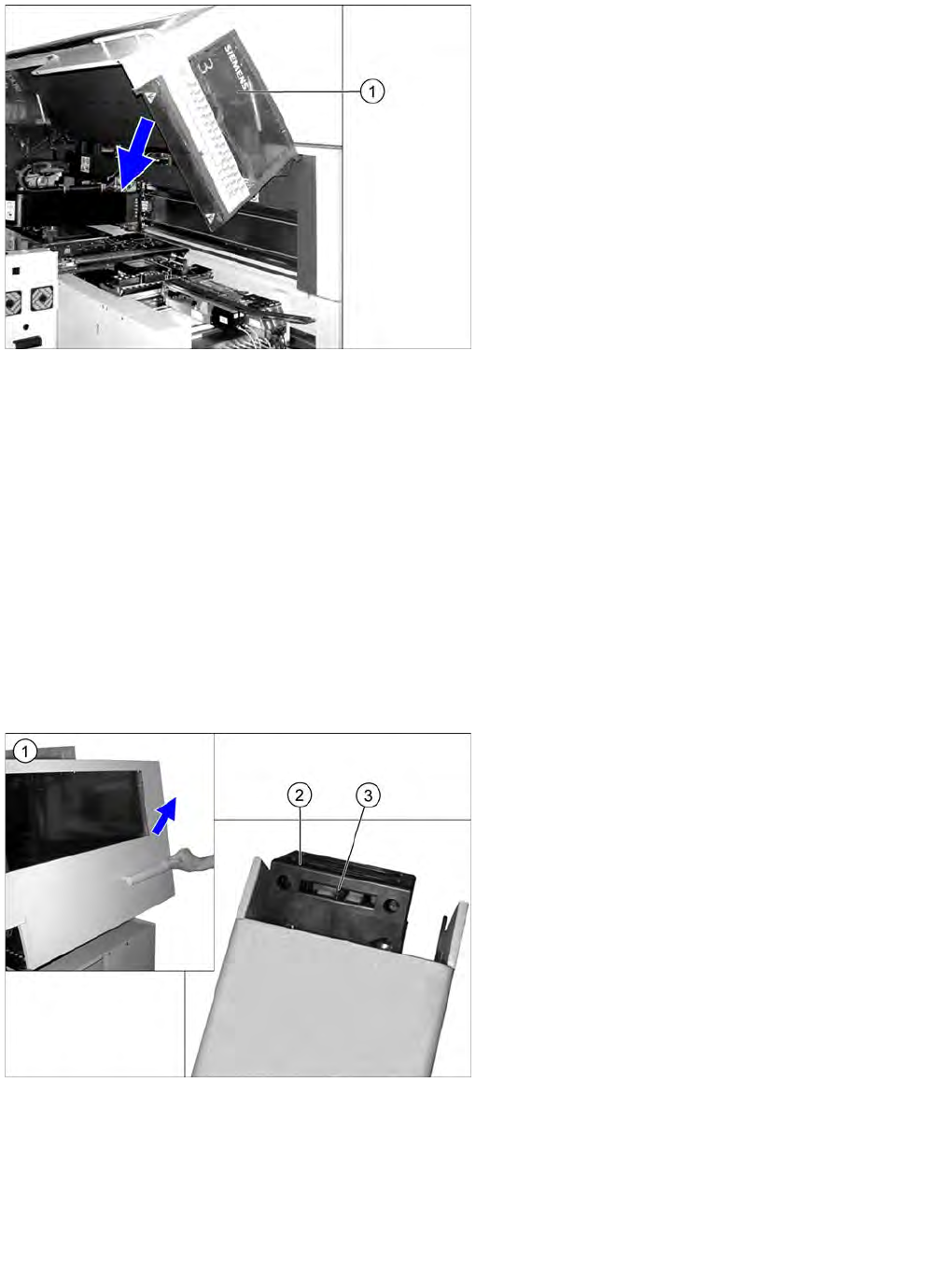
Protective cover switch
► Open the protective cover (1).
► Pull the protective cover approx. 30 cm downwards
and then release it again.
If the cover does not open completely again and if
there is play in the uppermost position (approx. 20
mm), replace the gas pressure shock absorbers.
For removal and installation details, refer to the
service manual for the respective machine.
► Pull the protective cover vertically to a position
between the top and bottom positions and then
release it again.
The cover must stay in position without help. If it
closes on its own, replace the gas pressure shock
absorbers.
For removal and installation details, read the service
manual for the respective machine.
► Close the protective cover.
► Repeat these steps for all protective covers.
► Open the protective cover (1). The other protective
cover must be closed.
► The controls must switch off immediately. You will
hear this clearly by the venting compressed air.
► Move the gantry in the X and Y directions. If the
control does not switch off or the gantry does not
move effortlessly, then the cover switch (2) may be
defective. In this case, replace the cover switch. For
removal and installation details, read the service
manual for the respective machine.
► Check the hood switch for damage, particularly the
plastic web (3) in the middle. If there is any damage,
replace the cover switch with a new one. For removal
and installation details, read the service manual for
the respective machine.
► Check that the actuator moves cleanly and
effortlessly into the switching unit. If this is not the
case, align the actuator and cover switch with respect
to one another.
► Repeat these steps for all cover switches.