4OM-1054-002.pdf - 第148页
3. 1 T ypical Description T able 4B4 Error ID Item Description 1 1040 * L CONVEYOR WIDTH LIMIT (+) LIMIT ERROR HAS BEEN DETECTED. ; BPH77 E/NR 1 1040 * L CONVEYOR WIDTH LIMIT (-) LIMIT ERROR HAS BEEN DETECTED. ; BPH77 E/…
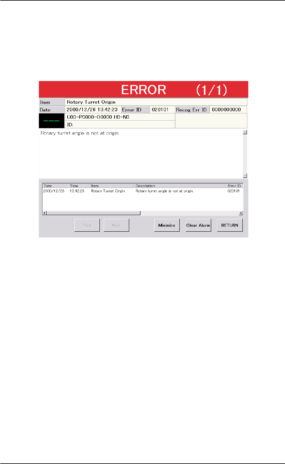
3. Troubleshooting after Error Window (Error ID)
Assuming "Error ID", "Item (Error Name)", and "Description" in the "ER-
ROR" window as an index, the system retrieves the related page of the
instruction manual.
Refer to "3.1 Typical Description" for the detailed description.
Fig. 4B9 Example of "ERROR" Window
0307-004 2-30
AGS01ETRP
3. Troubleshooting after Error Window
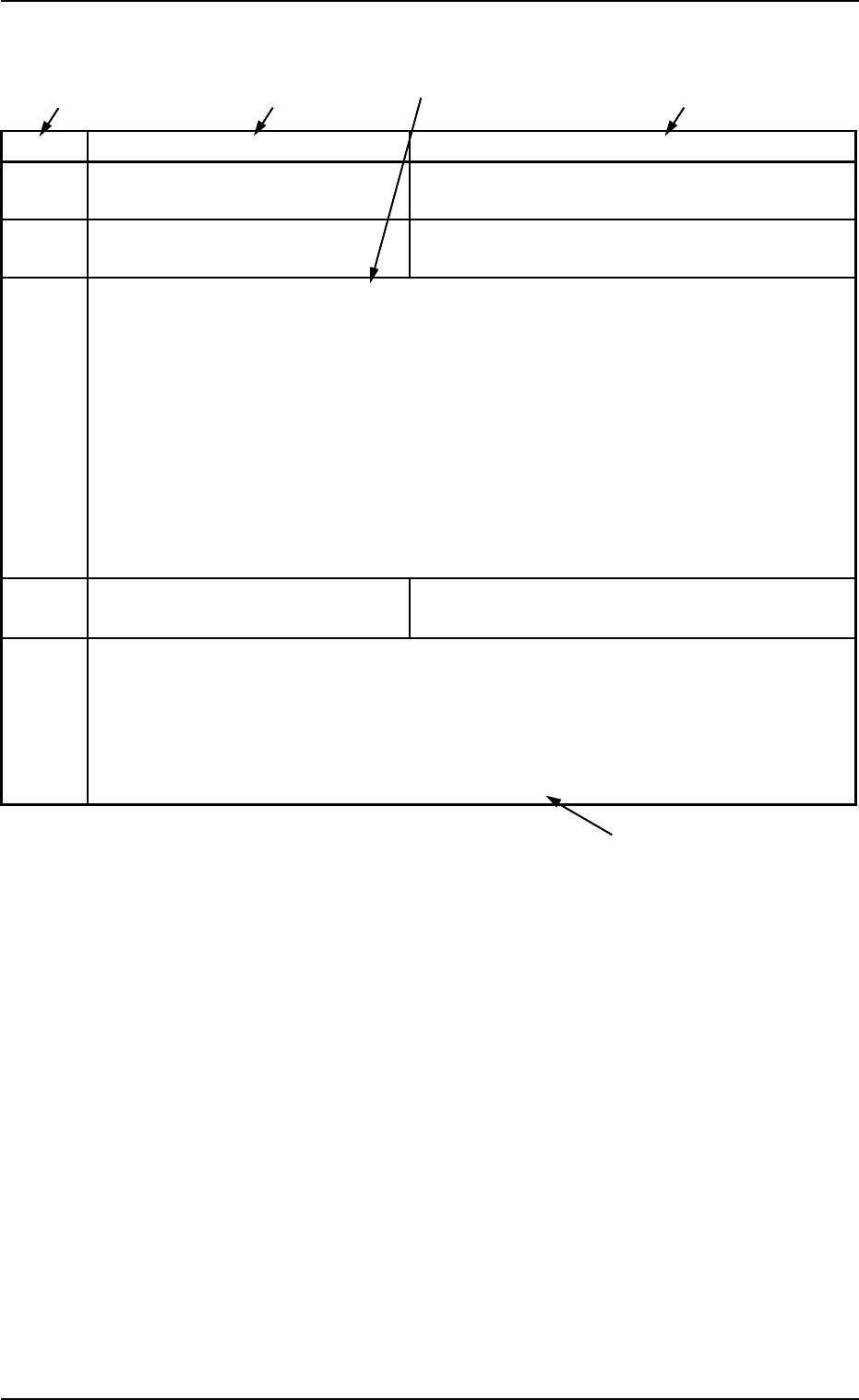
3.1 Typical Description
Table 4B4
Error ID Item Description
11040* L CONVEYOR WIDTH LIMIT (+) LIMIT ERROR HAS BEEN DETECTED.
; BPH77 E/NR
11040* L CONVEYOR WIDTH LIMIT (-) LIMIT ERROR HAS BEEN DETECTED.
; BPH77 E/NR
(Cause 1) An optical beam of the sensor is shielded.
(Cause 2) Dirt adheres to the sensor and the optical beam is shielded.
(Cause 3) The sensor is defective.
(Remedy 1) Turn off the power supply and move the conveyor width with the manual knob for
easier operation. Re-attach the light shield plate or the sensor securely (remove
the looseness).
(Remedy 2) Wipe off dirt on the sensor and zero the L conveyor again.
(Remedy 3) Replace the sensor with a new one.
12010* R CONVEYOR WIDTH ORIGIN OUTPUT SIGNAL FROM THE PULSE MOTOR DRIVER
WAS NOT DETECTED.
(Cause 1)
(Remedy 1)
(Continued to the next page)
*1 The error IDs (IDs displayed in the "ERROR" window) are described
in the numerical order.
"*" in the table will be filled with a numeric character.
*2 Described are the error name (item) and the description in the "ER-
ROR" window.
*3 Described are the causes and remedial procedures of the errors
in "*2 (Item and Description)".
The causes and remedies are correlated as follows.
(Cause 1)
ÆÆ
ÆÆ
Æ (Remedy 1)
(Cause 2)
ÆÆ
ÆÆ
Æ (Remedy 2)
(Cause 3)
ÆÆ
ÆÆ
Æ (Remedy 3)
*4 This indicates that the related contents are described subsequently
on the next page.
0211-004 2-31 AGS01ETRP
*4
*2
*3
*2
*1
3.1 Typical Description
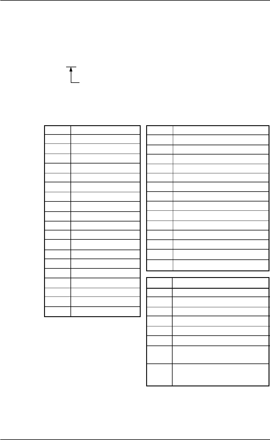
3.2 Error IDs and Controlled Areas
Basic System of Error IDs
An error ID is expressed by 6 digits (hexadecimal) as follows.
Major Classification of "Operation Axis", "Process Error",
and "Teaching Operation"
Error IDs and Controlled Areas
Table 4B5
Error ID Operation Axis Error ID Process Error
02 Rotary Turret 40 Safety Device
03
Component Pickup (Z) Axis 41 Data
04
Component Placement (Z) Axis 42 Conveyor
05 Table X 43 Self-Diagnostics 1
06 Table Y 44 Self-Diagnostics 2
07 X/Y Conveyor 45 Recognition Communication
08 Feeder Carriage #1 46 P.E.C. Recognition
09 Feeder Carriage #2 47 Pickup Error
0c Head 48 Component Recognition
0d Camera X 49 Control P.C.B.
0e Camera Y 4a Camera Teaching/Correction
0f P.C.B. Transfer 4b Others
10 X/Y Chute Width 4c Unit P.C.B. B.B.R. Mode
11 L Conveyor Width 4f Program Error
12 R Conveyor Width
13 Support Pin U/D Error ID Teaching Operation
14 P.C.B. Locate Lever 60 Nozzle Position
15 L2 Conveyor 61 Lighting for Component Recognition
16 R2 Conveyor 62 Nozzle Level
63
Head Center Offset/Nozzle Position
64 Master Head Offset
65 Head Origin Offset
66 Teaching (Dust/Dirt Detection (Cam-
era))
67 Teaching (Dust/Dirt Detection
(Diffusion Plate/Nozzle))
0303-005 2-32 AGS01ETRP
3.2 Error IDs and Controlled Areas