4OM-1054-002.pdf - 第21页
1. 3 Maintenance Spots 1.3.1 General View Refer to "1.3.2" and after for details. Fig. 4A5 T op View of Machine 1.3 Maintenance Spots 021 1-004 1- 8 AGS01ETRP • Before performing maintenance work, turn off the …
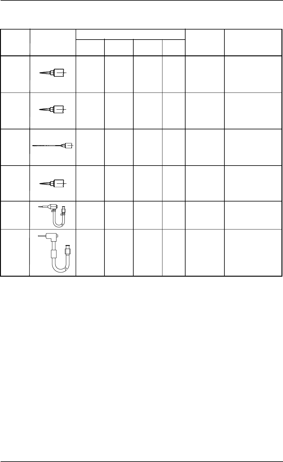
Nozzle for Dispense Gun DG10KIT
Table 4A7
Standard Shape Part No. Remarks
No.14 1 0 1 2 630 062 2591
(Color:
Olive)
No.18 1 0 0 1 630 062 2607
(Color:
Green)
No.19 0 1 1 2 630 062 2621
(Color:
Brown)
No.20 1 0 1 2 630 062 2614
(Color:
Pink)
HL2 Type 0 1 0 1 630 105 4445
RR Type 0 1 0 1 630 110 5307
Grease and Number of Required Nozzles
For DAPHNE
EPONEX
GREASE No. 1
For NEW
MOLYNOC
GREASE No. 1
Total
Frequency
in Use
For DAPHNE
EPONEX
GREASE No. 3
1.2 Preparation for Maintenance
0111-003 1-7 AGS01ETRP
Maker: Sanei Tech
Inside Diameter: φ1.6
Tapered Nozzle
#5114TT-B
Maker: Sanei Tech
Inside Diameter: φ0.84
Tapered Nozzle
#5118TT-B
Maker: Nipro
Inside Diameter: φ0.79
Length: 65 mm
Flattened End
Maker: Sanei Tech
Inside Diameter: φ0.58
Tapered Nozzle
#5120TT-B
Maker: SHC
Maker: SHC
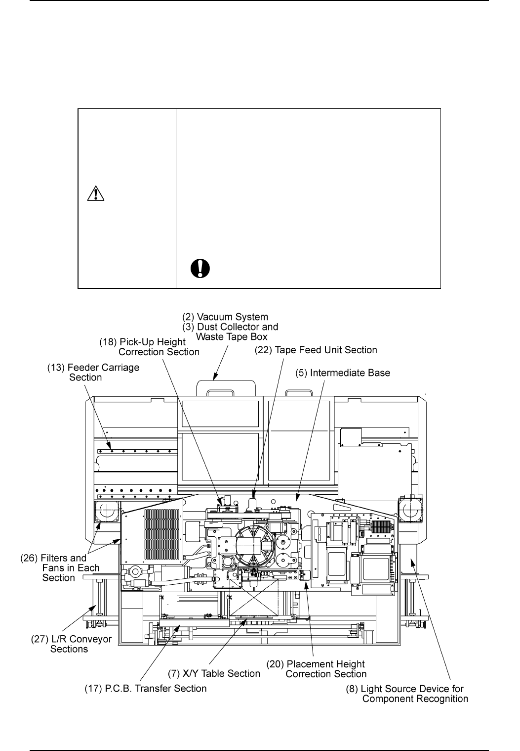
1.3 Maintenance Spots
1.3.1 General View
Refer to "1.3.2" and after for details.
Fig. 4A5 Top View of Machine
1.3 Maintenance Spots
0211-004 1-8 AGS01ETRP
• Before performing maintenance work, turn off the
power and air sources and lock the power breaker
using the padlock.
• Designate a person who can have charge of the
padlock key.
• The cover of the machine must be detached for the
maintenance work.
After the maintenance work, be sure to attach the
cover.
CAUTION
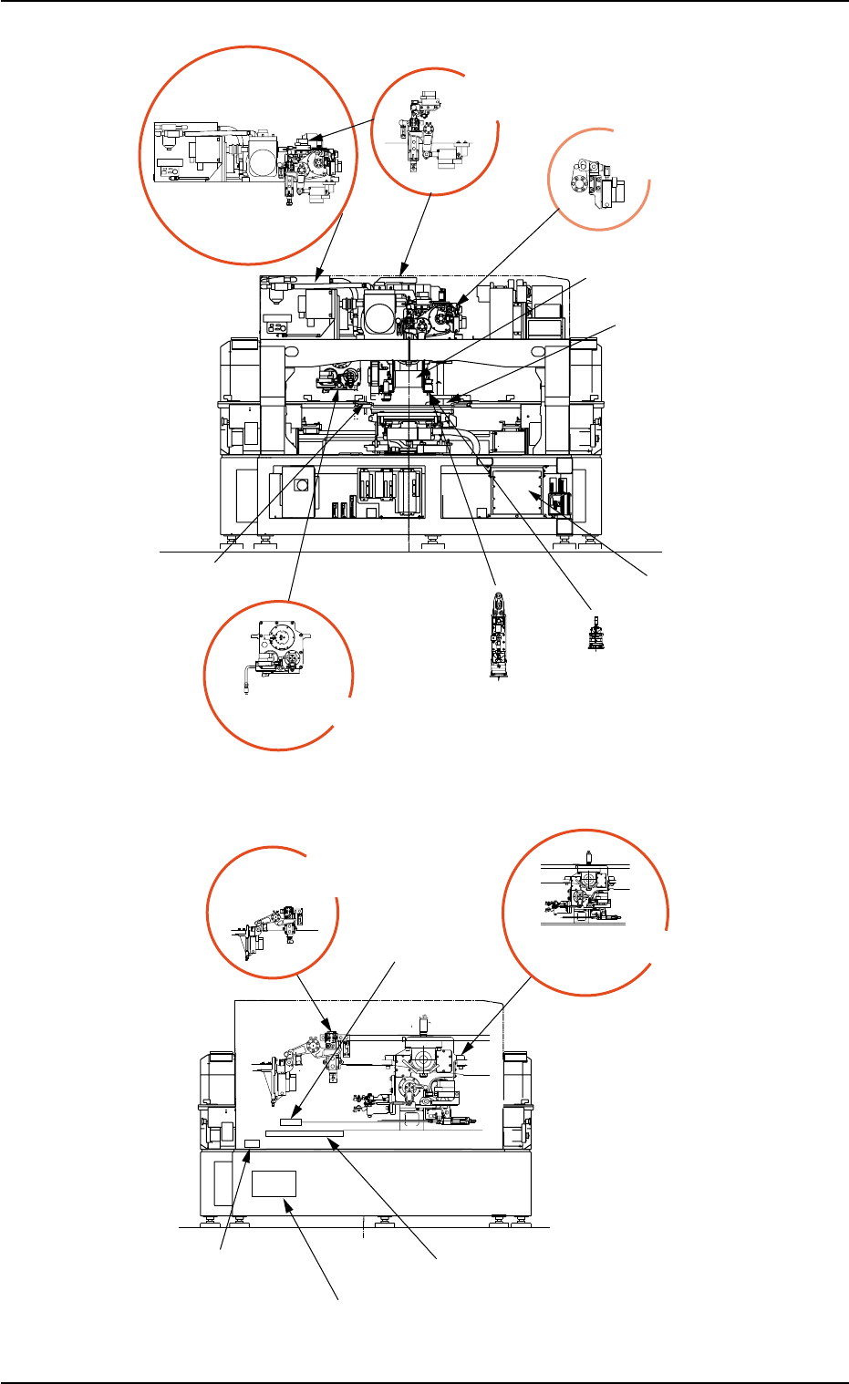
1.3 Maintenance Spots
0111-003 1-9 AGS01ETRP
(15) Nozzle Change
Section
(14) Placement Change
Correction Section
(21) Placement
Up/Down Section
(11) Main Body
Driving Section
(9) Head Section
(5) Component
Receiving Box
(24) Head Up//Down Section
(25) Control Box
Section
(4) Component
Recognition Section
(23) Nozzle Guide Section
(19) Pick-Up Up/Down
Section
(16) Nozzle Change/Return
Section
(12) Cutter Section
(1) Air Source
(10) Linear Measure
Detection Section
(6) Cutter Section
Component Drop Prevantion Cover
Fig. 4A7 Front View of Machine
Fig. 4A8 Rear View of Machine