4OM-1054-002.pdf - 第22页
1.3 Maintenance Spots 01 1 1-003 1- 9 AGS01ETRP (15) Nozzle Change Section (14) Placement Change Correction Section (21) Placement Up/Down Section (1 1) Main Body Driving Section (9) Head Section (5) Component Receiving …
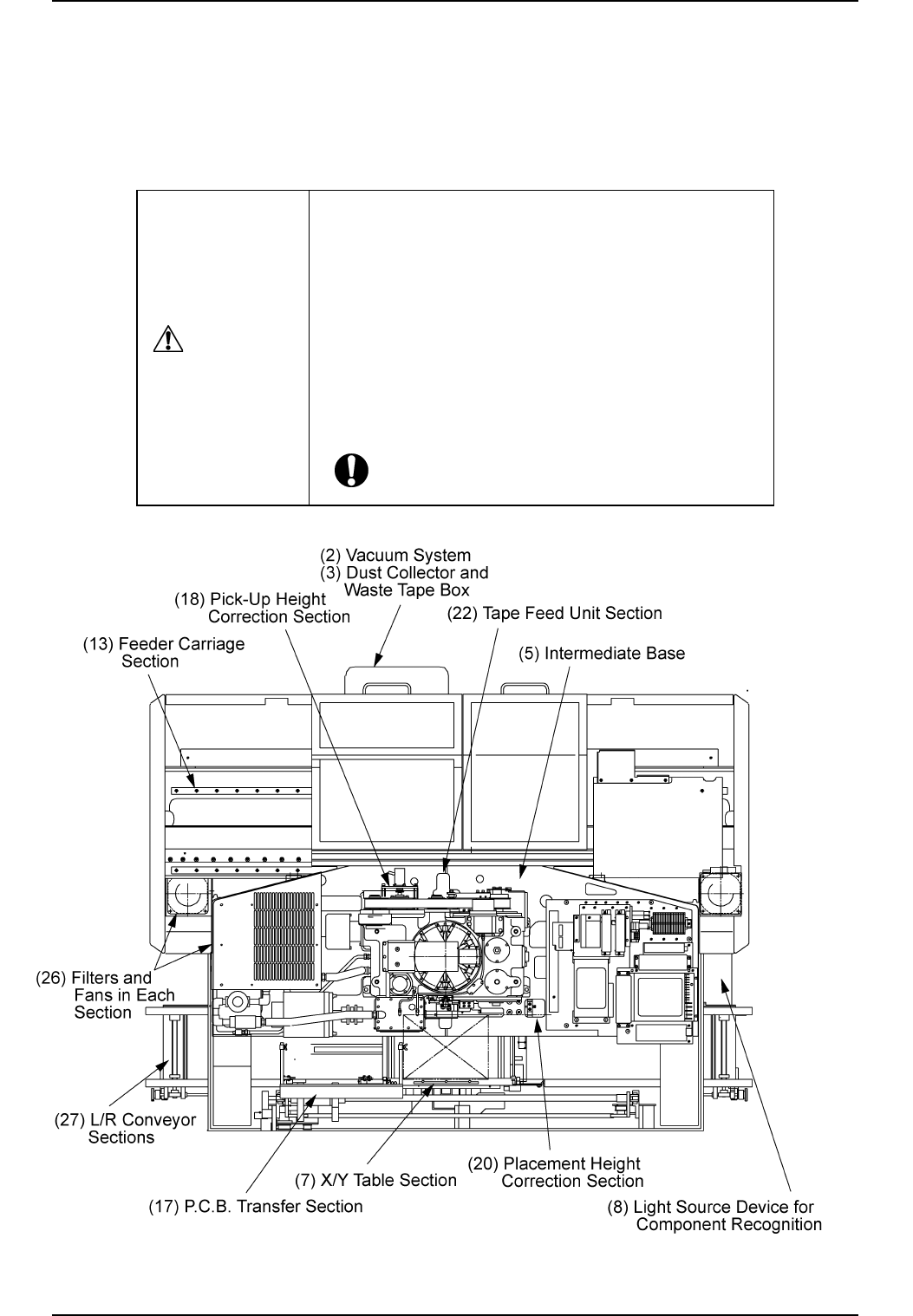
1.3 Maintenance Spots
1.3.1 General View
Refer to "1.3.2" and after for details.
Fig. 4A5 Top View of Machine
1.3 Maintenance Spots
0211-004 1-8 AGS01ETRP
• Before performing maintenance work, turn off the
power and air sources and lock the power breaker
using the padlock.
• Designate a person who can have charge of the
padlock key.
• The cover of the machine must be detached for the
maintenance work.
After the maintenance work, be sure to attach the
cover.
CAUTION
1.3 Maintenance Spots
0111-003 1-9 AGS01ETRP
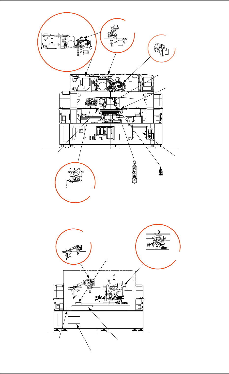
(15) Nozzle Change
Section
(14) Placement Change
Correction Section
(21) Placement
Up/Down Section
(11) Main Body
Driving Section
(9) Head Section
(5) Component
Receiving Box
(24) Head Up//Down Section
(25) Control Box
Section
(4) Component
Recognition Section
(23) Nozzle Guide Section
(19) Pick-Up Up/Down
Section
(16) Nozzle Change/Return
Section
(12) Cutter Section
(1) Air Source
(10) Linear Measure
Detection Section
(6) Cutter Section
Component Drop Prevantion Cover
Fig. 4A7 Front View of Machine
Fig. 4A8 Rear View of Machine
1.3.2 Understanding of Maintenance Items on Each Section
Clarified in this session are each individual spots of the machine to be
maintained.
Refer to "1.5 Maintenance Check List" for periodic maintenance.
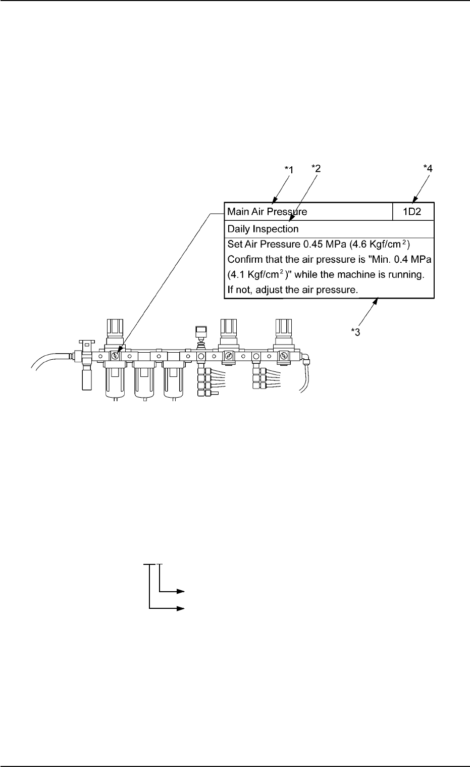
View of Inspection, Cleaning, and Lubrication Spots
(Example of Identification)
Fig. 4A9
*1: Maintenance Spot
*2: Cycle and Contents of Maintenance
*3: Details of Maintenance
*4: Maintenance Spot No.
These are used in "1.5 Maintenance Check List".
Display 1D2
Number (0, 1, 2 …)
Cycle of Maintenance
1D: Every Day
1W: Every Week
1M: Every Month
3M: Every 3 Months
6M: Every 6 Months
1Y: Every Year
1.3 Maintenance Spots
0211-004 1-10 AGS01ETRP