4OM-1054-002.pdf - 第29页
(6) Cutter Section Component Drop Prevention Cover Fig. 4A15 T op View of Machine 1.3 Maintenance Spots 021 1-004 1-16 AGS01ETRP Component Drop Prevention Cover 1D9 Daily Cleaning When components are scattered over the c…
1.3 Maintenance Spots
0211-004 1-15 AGS01ETRP
Fig. 4A14-1 Front View of Machine
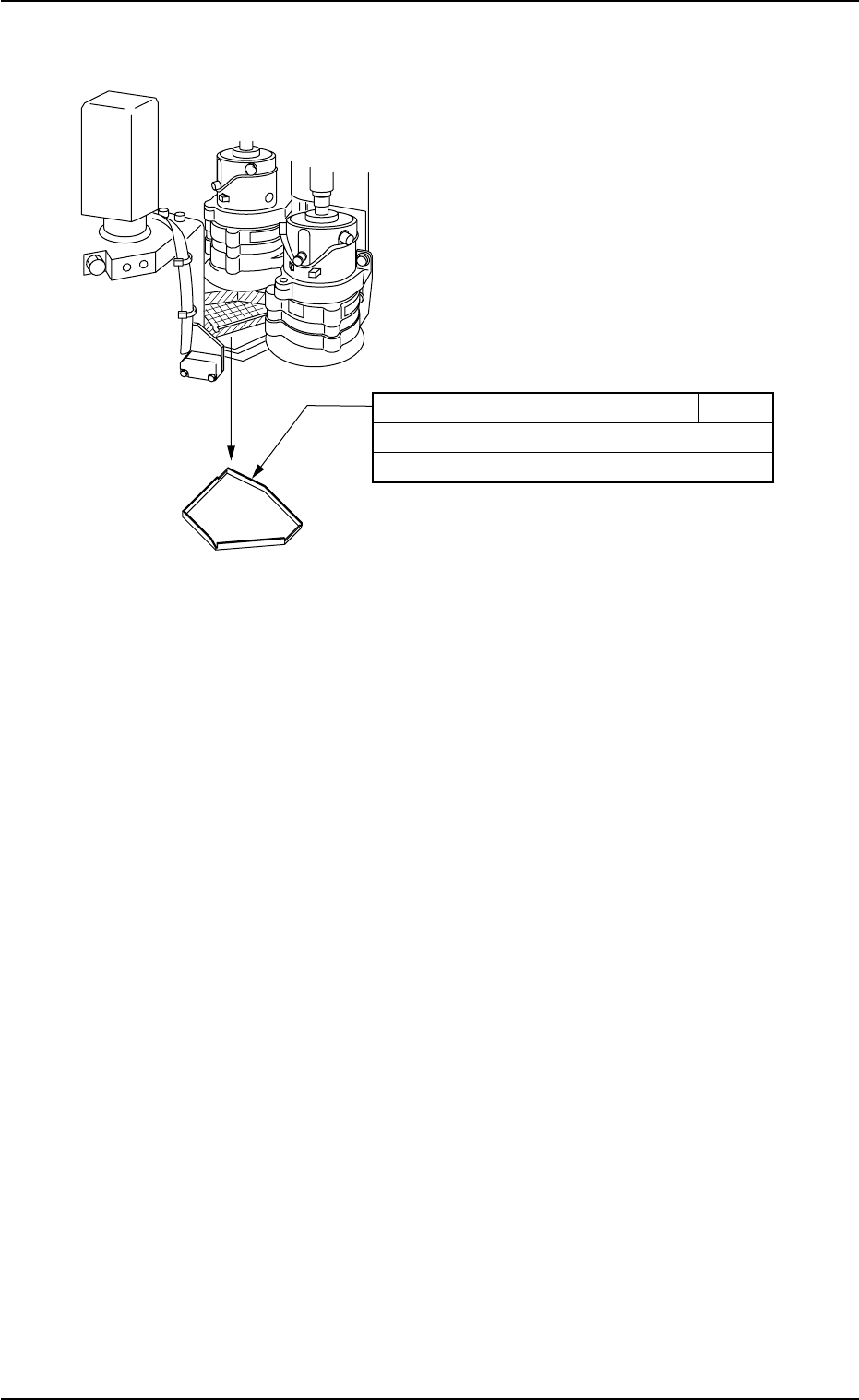
Component Receiving Box 1D8
Daily Cleaning
Clean with a vacuum cleaner.
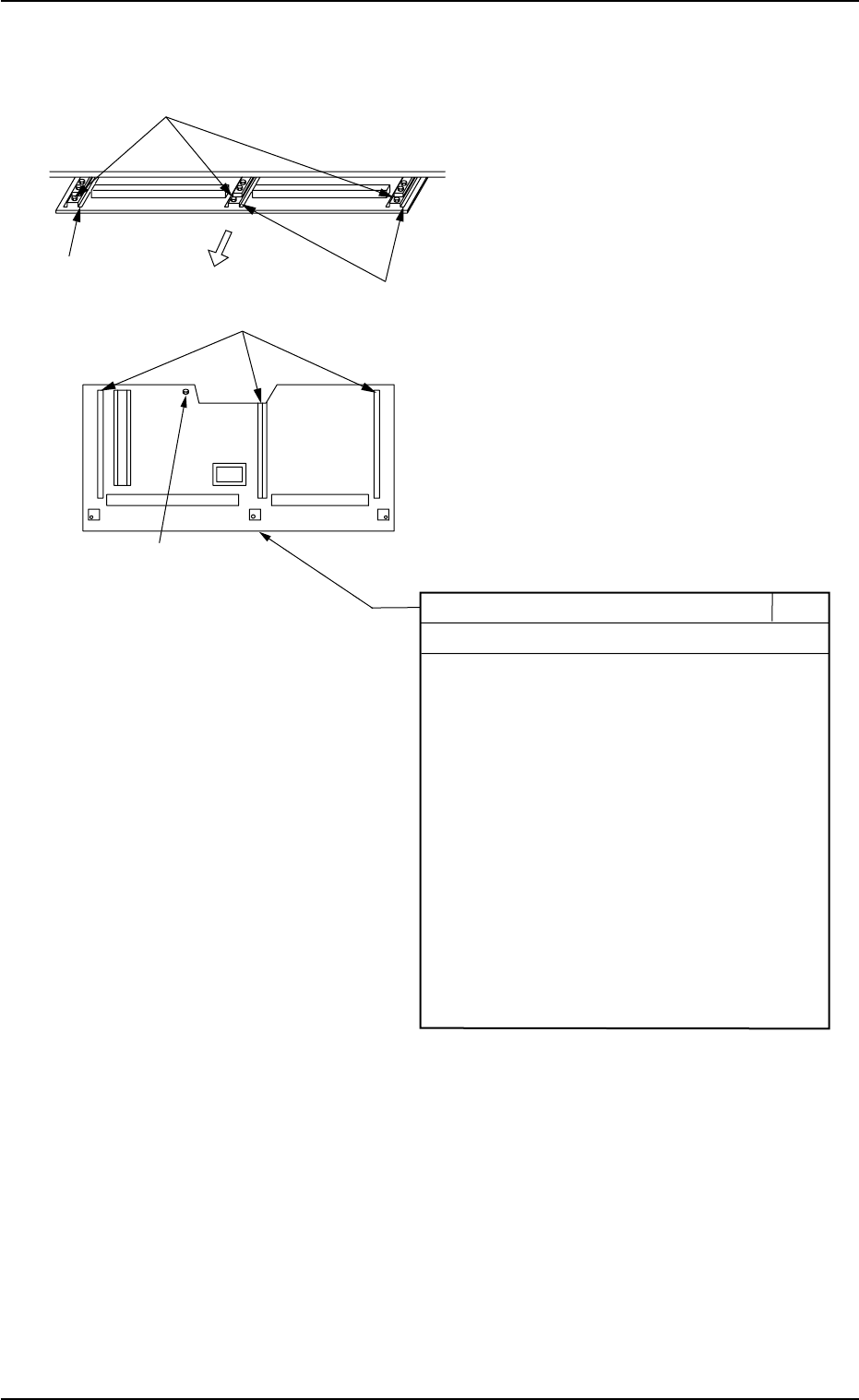
(6) Cutter Section Component Drop Prevention Cover
Fig. 4A15 Top View of Machine
1.3 Maintenance Spots
0211-004 1-16 AGS01ETRP
Component Drop Prevention Cover 1D9
Daily Cleaning
When components are scattered over the
cover, follow the steps below to remove them.
1. Set the timing angle of the rotary turret to
approx. 200 degrees and turn off the power
supply before cleaning work.
2. Remove the four screws and pull out the
cover toward the rear side of the machine.
3. Clean the cover with a vacuum cleaner, etc.
4. Attach the cover to the machine such that
the rail section of the cover is correctly
inserted into the guide section of the machine.
5. Attach the four screws.
Pull out.
Guide Section
Guide Section
Screws
Rail Section
Screw
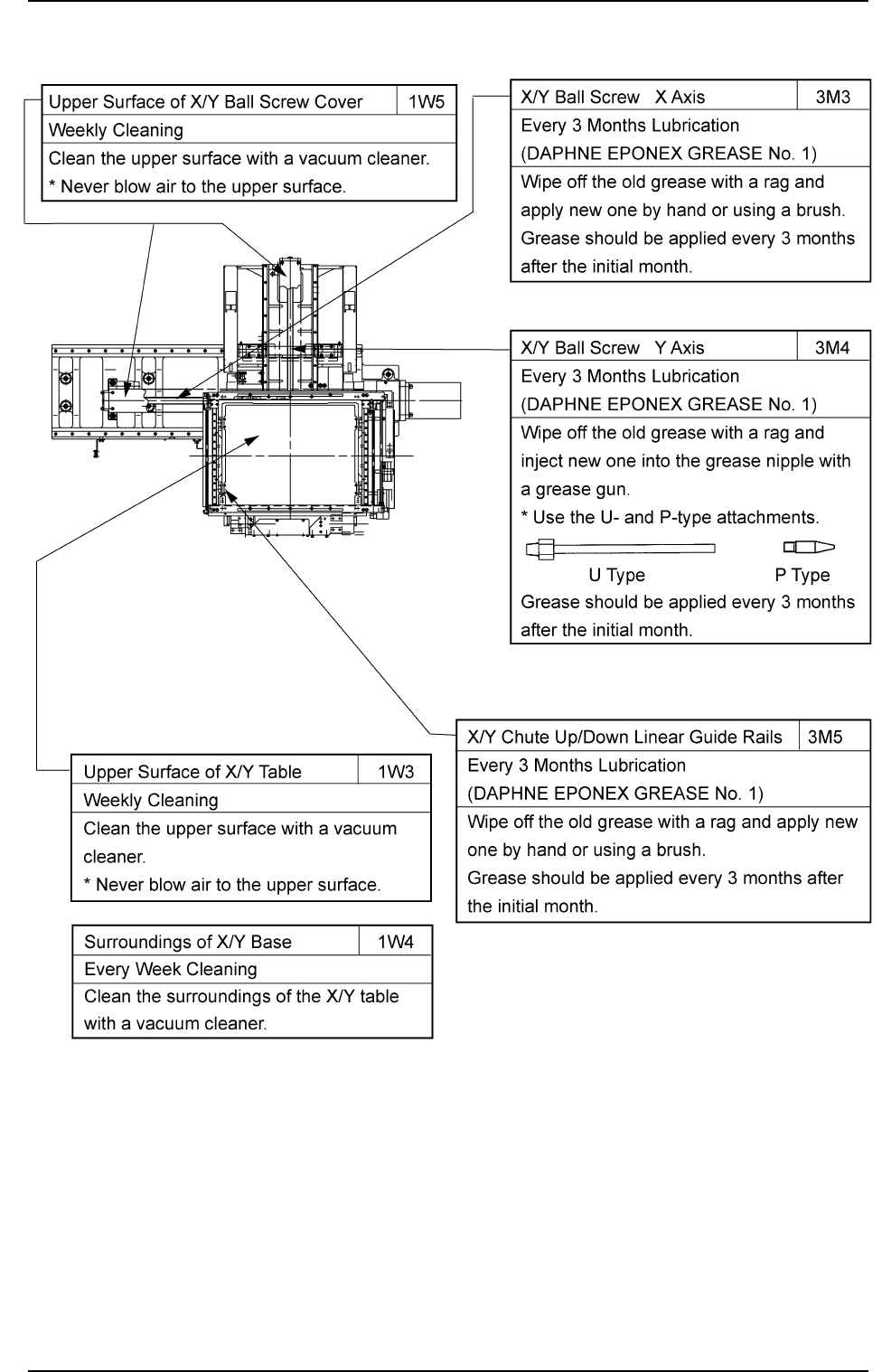
(7) X/Y Table Section
1.3 Maintenance Spots
0211-004 1-17 AGS01ETRP
Fig. 4A16