00191099-01.pdf - 第51页
Component B ar-Code Sc anner (Optional) Retrofitting Instructions SIPLACE 80 / S-23 (HM) / HS-50 Issue 06/00 2.9 Retrofitting Sequence on S IPLACE HS-50 51 Fig. 2.9.2 Plug-In Power Supply Module for H S-50: Detaching t…
Retrofitting Instructions SIPLACE 80 / S-23 (HM) / HS-50 Component Bar-Code Scanner (Optional)
2.9 Retrofitting Sequence on SIPLACE HS-50 Issue 06/00
50
5HWURILWWLQJ6HTXHQFHRQ6,3/$&(+6
+DUGZ DU H,QVWDOODWLRQ
Å Turn the machine OFF, isolate the machine from the mains and turn OFF the flow of com-
pressed air at the compressed air unit (see DANGER text in Section 2.2).
Å Wait until the voltage decays.
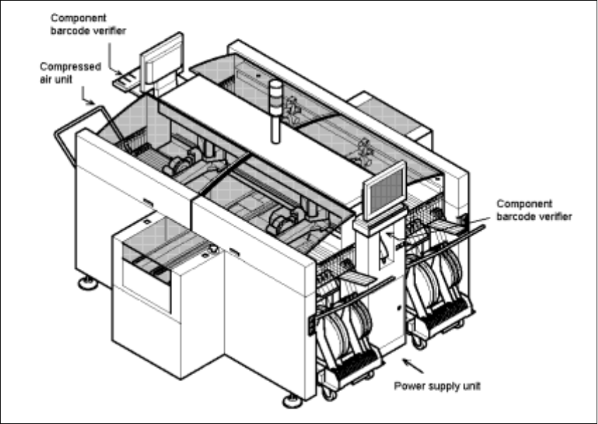
Fig. 2.9.1 Overall View of the SIPLACE HS-50: Orientation, Retrofit the Comp.Bar-Code Scanner
Å Open the machine frame doors on the plug-in power supply component and on the com-
pressed air unit.
Å For the work inside the machine frame, comply with the stricter safety regulations DIN EN
60204, Part 1 (see Section 2.2).
Component Bar-Code Scanner (Optional) Retrofitting Instructions SIPLACE 80 / S-23 (HM) / HS-50
Issue 06/00 2.9 Retrofitting Sequence on SIPLACE HS-50
51
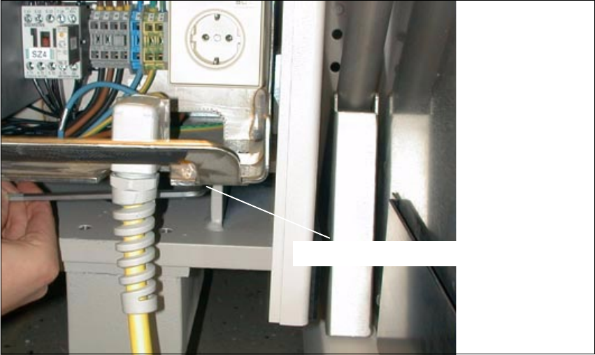
Fig. 2.9.2 Plug-In Power Supply Module for HS-50: Detaching the Plug-In Module
Å At the Bottom Right, loosen the screw fastening the plug-in power supply module (socket hex
head cap screw M8 / size 6).
6RFNHWKH[KHDGVFUHZ0
Retrofitting Instructions SIPLACE 80 / S-23 (HM) / HS-50 Component Bar-Code Scanner (Optional)
2.9 Retrofitting Sequence on SIPLACE HS-50 Issue 06/00
52
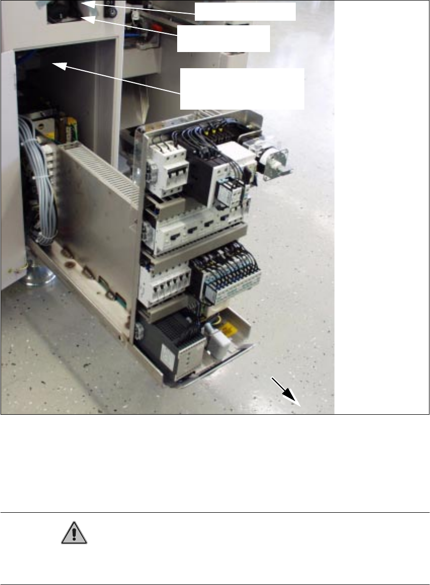
Fig. 2.9.3 Pulling Out the Plug-In Power Supply Module; Installation Side Comp. Bar-Code Scanner
Å Pull the plug-in power supply module out as far as possible (see Fig. 2.9.3).
This requires a rather large amount of force.
When it is pulled out, the module projects past the guides.
CAUTION
The plug-in power supply module must be covered quickly and carefully to avoid any short-circuit
due to a dropped tool, etc.
scanner
Signal filter to be
attached
component bar-code
Cables to be attached
Hand-held scanner