00191099-01.pdf - 第54页
Retrofitting I nstructions SIPLACE 80 / S-23 (HM) / HS-50 Component Bar-Code Scanner (Optional) 2.9 Retrofitti ng Sequence on SIPLACE HS-50 Issue 06/00 54 Fig. 2.9. 5 Block Diagram: Connection of the Component Bar- Code …
Component Bar-Code Scanner (Optional) Retrofitting Instructions SIPLACE 80 / S-23 (HM) / HS-50
Issue 06/00 2.9 Retrofitting Sequence on SIPLACE HS-50
53
Å In addition to the protective measures to be taken as per DIN EN 60204, Part 1, also cover the
plug-in power supply module with a heavy cloth (see CAUTION, above).
Fig. 2.9.4 Mounting the Signal Filter in the Indentation in the Machine Base
Å Place one portion of the adhesive Velcro fastener from the retrofit kit on the horizontal surface
of the indentation (Section 2.3.4) as shown above.
Å Fasten the other portion of the Velcro fastener to the two signal filters from the retrofit kit.
Å Fasten the signal filters to the two operator sides (see "Overview", Fig. 2.9.1) as shown in Fig.
2.9.4.
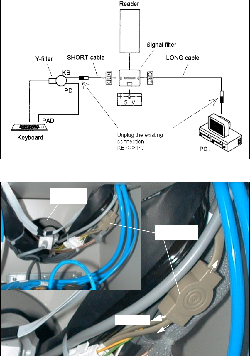
Å Unplug the existing plug-and-socket connection "Computer cable <-> Y-filter (KB)": see block
diagram, Fig. 2.9.5 and Fig. 2.9.6.
6LJQDOILOWHU
Strip of adhesive
Velcro
Retrofitting Instructions SIPLACE 80 / S-23 (HM) / HS-50 Component Bar-Code Scanner (Optional)
2.9 Retrofitting Sequence on SIPLACE HS-50 Issue 06/00
54
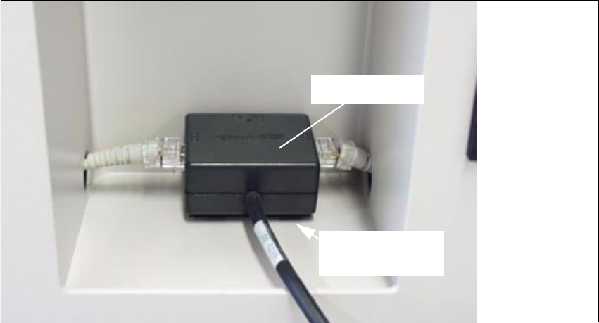
Fig. 2.9.5 Block Diagram: Connection of the Component Bar-Code Scanner to the HS-50
Fig. 2.9.6 BEFORE: Disconnect Computer Cable on Y-filter (KB) (Example = Compressed Air Side)
<ILOWHU
.H\ERDUG
3$'
.%
3'
Cable gland
&20387(5

Component Bar-Code Scanner (Optional) Retrofitting Instructions SIPLACE 80 / S-23 (HM) / HS-50
Issue 06/00 2.9 Retrofitting Sequence on SIPLACE HS-50
55
Å Hang the hand-held scanner in the bracket in the depression.
Å Connect the cables for the signal filter on BOTH operator sides as shown in the block diagram
above.
Å Tie the cable package/cable harness very neatly and securely with cable ties as shown in Fig.
2.9.7 and Fig. 2.9.8.
Å Be particularly careful to tie the cables above the plug-in power supply module in such a man-
ner as to preclude any damage to the cables later when the plug-in module is pushed in.
CAUTION
Do not utilize an open flame during the following work of cleaning with isopropyl alcohol.
Å Degrease the assembly surfaces for the two adhesive mounting pedestals (position: see Fig.
2.9.7 and Fig. 2.9.8) with isopropyl alcohol. Dispose of the cloth in an appropriate manner.
Å Mount the mounting pedestals for the cable ties (see Section 2.4.1) on both operator sides.
Use the cable tie to fasten the individual plug-and-socket connections as shown in Fig. 2.9.7
and Fig. 2.9.8 respectively.
CAUTION
Do not pinch any cables while sliding in the plug-in power supply module.
Å Remove the cloth and carefully push in the power supply module.
Å Use the socket hex head cap screw M8 (size 6) to refasten the power supply module from the
bottom: see Fig. 2.9.2.
Å Close the doors of the machine base.