5OM-1625-003_w.pdf - 第74页
5OM-1603 1-19 Pneumatic and Mounting Diagrams NOZZLE1 NOZZLE2 NOZZLE3 7 10 1 1 12 Multi-Functional Head Unit (Mounting Diagram) 1 102-001-(03G00) No. Name Q’ty No. Name Q’ty No. Name Q’ty No. Name Q’ty 7 Regulater 1 10 S…
5OM-1603
1-18
Pneumatic and Mounting Diagrams
5
5
6
9
2
11
10
10
10
1
2
11
12
12
1
2
11
12
1
7
8
3
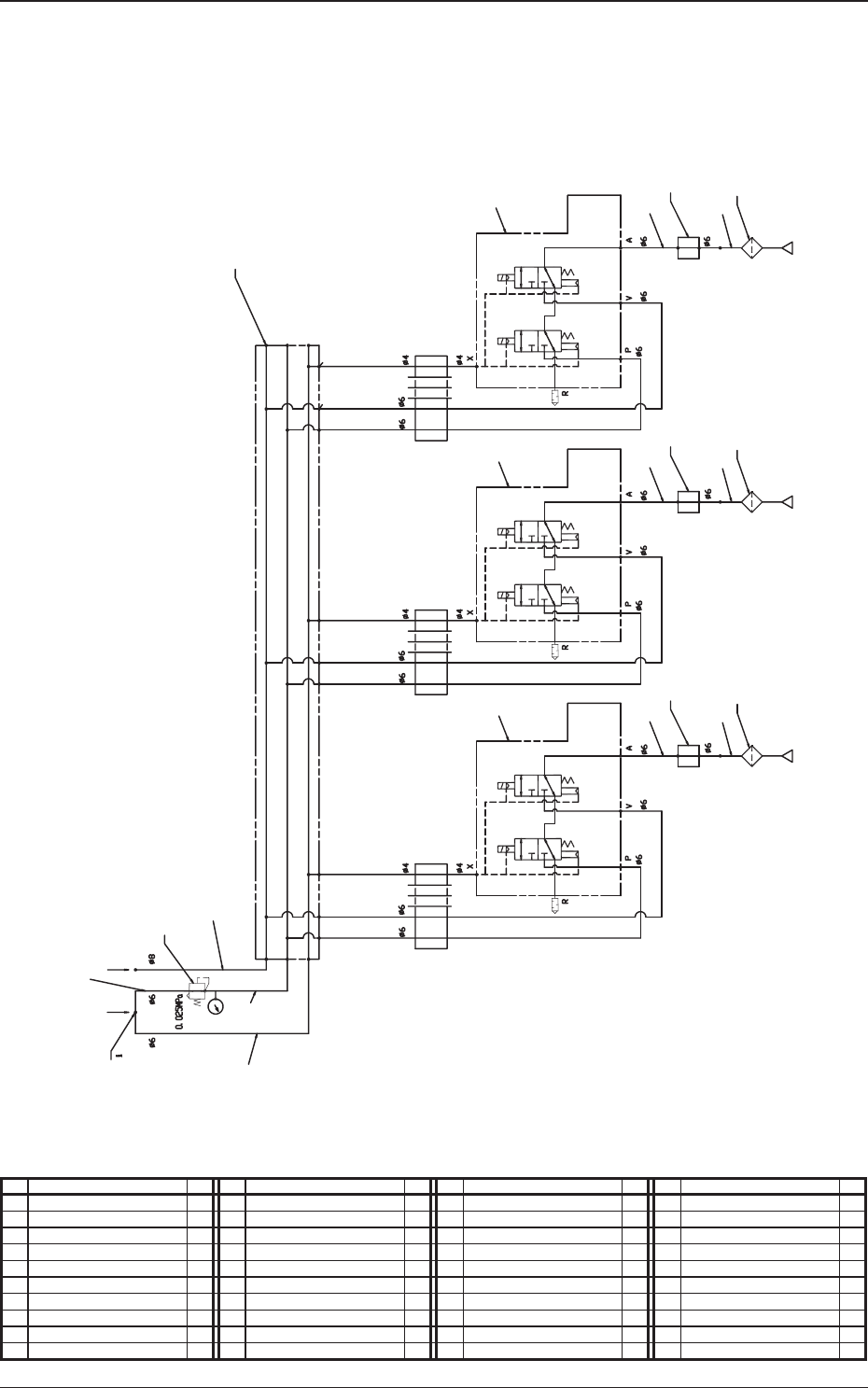
Nozzle 3Nozzle 2Nozzle 1
Air IN
Vacuum
Set up
Multi-Functional Head Unit (Pneumatic Diagram)
No. Name Q’ty No. Name Q’ty No. Name Q’ty No. Name Q’ty
1 Tube
f
6 1 11 Vacuum Sensor 3
2 Tube
f
6 1 12 Vacuum Filter 3
3 Tube
f
6 1
4 Tube
f
6 1
5 Tube
f
6 1
6 Tube
f
8 1
7 Regulater 1
8 Union Y 1
9 Manifold Unit 1
10 Solenoid Valve Unit 3
1102-001-(03G00)
5OM-1603
1-19
Pneumatic and Mounting Diagrams
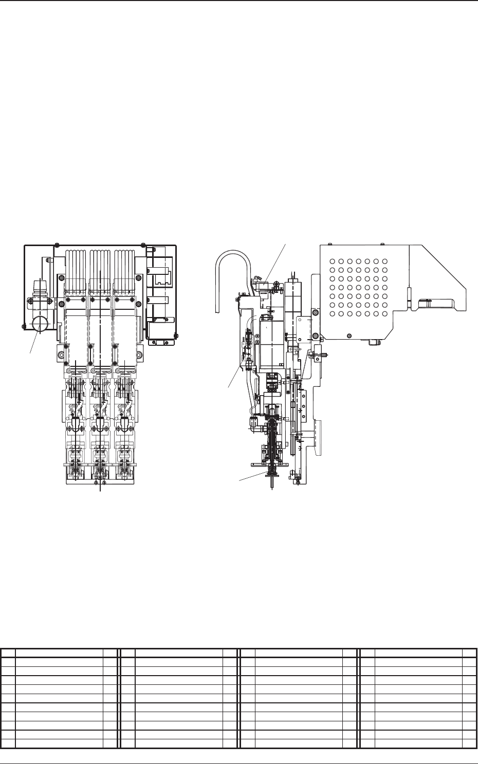
NOZZLE1 NOZZLE2 NOZZLE3
7
10
11
12
Multi-Functional
Head Unit (Mounting Diagram)
1102-001-(03G00)
No. Name Q’ty No. Name Q’ty No. Name Q’ty No. Name Q’ty
7 Regulater 1
10 Solenoid Valve Unit 3
11 Vacuum Sensor 3
12 Vacuum Filter 3
5OM-1603
1-20
Pneumatic and Mounting Diagrams
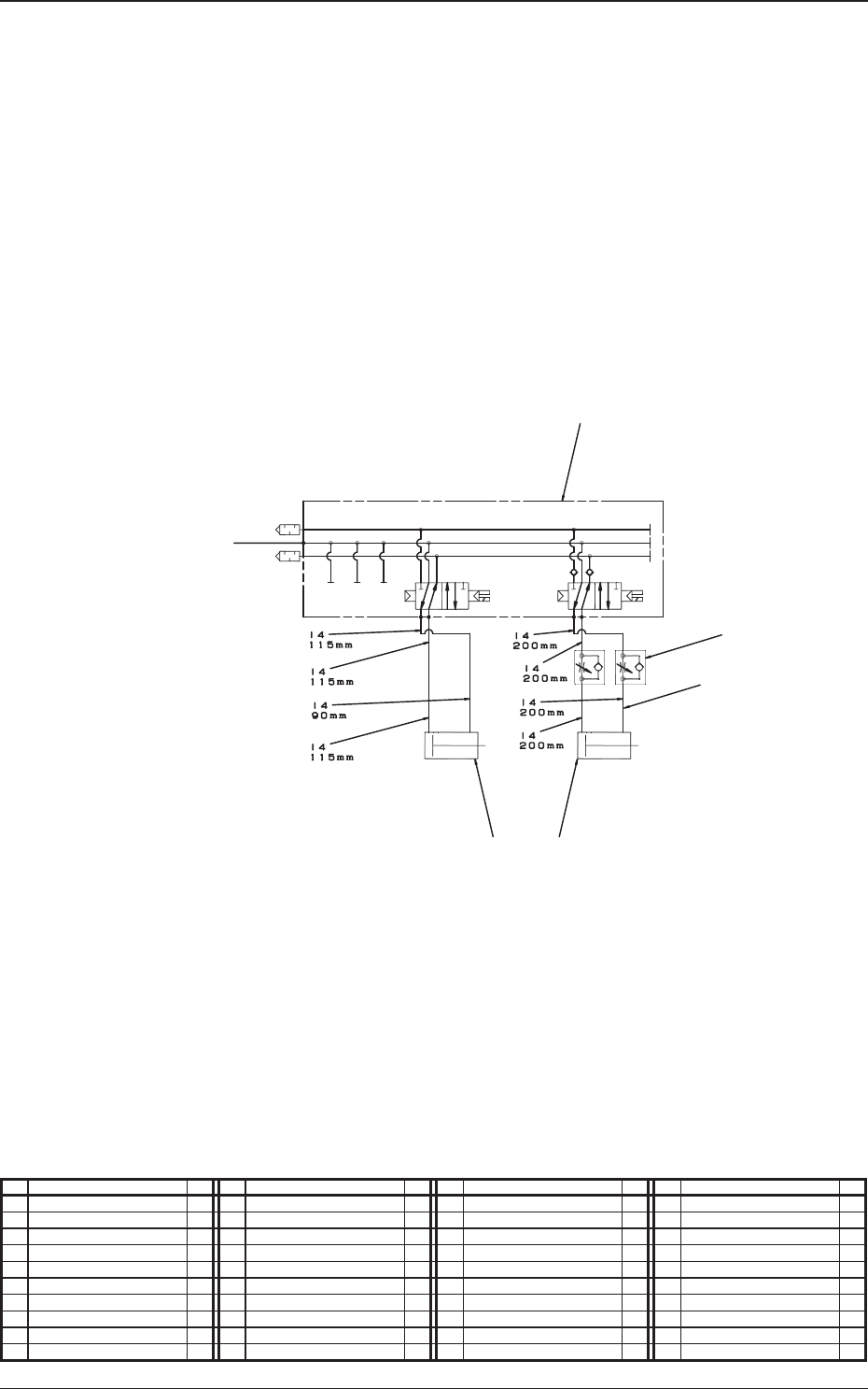
Nozzle Stocker for Multi-Functional Nozzle (Pneumatic Diagram)
No. Name Q’ty No. Name Q’ty No. Name Q’ty No. Name Q’ty
1 Tube
f
4 1
2 Solenoid Valve 1
3 Speed Controller 2
4 Cylinder 1
5 Cylinder 1
1102-001-(08303)
4
From the Inside of Whole Base
Stocker 1 U/D Shutter 1 Open/Close
5
2
3
1