00198765-02_VD_SSW_713.1_R20-1_EN_DE - 第12页
Station Software 713.1 (R 20-1) / V ersion Description 05/2020 Edition 12 4.3 Configuring Tolerance Va lues for Resetting t he Conveyo r Width Compatible mode: Complete If the Automatic Width Adjustment option has bee n …
Station Software 713.1 (R20-1) / Version Description 05/2020 Edition
11
When generating a PDF report, the statistical data in the PDF matches the sigma level that has
been selected when the PDF report has been generated. You can change the sigma level after
generating a PDF report, but please note that if you want to generate a new PDF report with the
new sigma level, you need to repeat the measurement.
The general ACT behavior is not changed by this enhancement, i.e. the values for the offset
correction are independent from the selected sigma level. To repeat the manual correction, a new
ACT placement is needed.
For further information on ACT, please refer to the ACT User Manual, item no. [00196351-xx].
4.2 Support of SIPLACE TX2 V2 HD / SIPLACE TX2i V2 HD
The hardware upgrade kit High Density option package TX, item no. [588510-xx] for the
SIPLACE TX2 V2 / TX2i V2 is supported.
With a conveyor update and corresponding X-Fiducials contained in the hardware upgrade kit, a
SIPLACE TX2 V2 / TX2i V2 can be remodeled to a SIPLACE TX2 V2 HD / TX2i V2 HD. These
upgraded machine types can perform high density placement.
Original Machine
Type
Placement Heads
Upgraded
Machine Type
SIPLACE TX2 V2
2x CPP placement heads (low position)
with SST30
TX2 V2 HD
2x CPP placement heads (low position)
with SST45
1x CPP placement head (low position)
with SST30 + 1x CPP placement head
(low position) with SST45
SIPLACE TX2i V2
2x CP20 P2 placement heads with SST48
TX2i V2 HD
2x CP20 P2 placement heads with SST49
1x CP20 P2 placement head with SST48
+ 1x CP20 P2 placement head with
SST49 (mixed camera configuration)
Table 4-1: Overview of high density placement upgrade option per machine type
NOTICE
When upgrading a machine type, the station software needs to be reinstalled on that
machine.
Restrictions
– The new machine types do not support Smart Pin Support.
Station Software 713.1 (R20-1) / Version Description 05/2020 Edition
12
4.3 Configuring Tolerance Values for Resetting the Conveyor Width
Compatible mode: Complete
If the Automatic Width Adjustment option has been activated on the Line Control GUI and the
conveyor width of the lane differs from the width specifications in the recipe (e.g. because it has
been manually changed for maintenance), the conveyor width is automatically reset to the width
specifications from the recipe at the start of production.
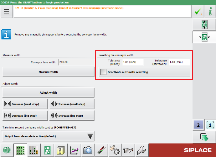
But even if the Automatic Width Adjustment option is deactivated, the conveyor width is reset to
the width specified in the recipe at the start of production if the conveyor width has been manually
changed further than a configured tolerance allows. The tolerance values can be specified in the
Tolerance fields under Resetting the conveyor width in the Width settings of the respective
lane. If the Automatic Width Adjustment option is deactivated on the Line Control GUI and you
do not want the conveyor width to be automatically reset at the start of production, you can use the
Deactivate automatic resetting option under Resetting the conveyor width.
Figure 4-2: Configuring tolerance values for resetting the conveyor width
By default, the conveyor width is allowed to differ by 1 mm from the width specifications in the
recipe. The smallest possible value is 0.0 mm (no deviation allowed). Negative values are not
allowed. The biggest possible value is 10 mm.
Restrictions
– The station can only adjust the width while no board is in the respective lane.
Station Software 713.1 (R20-1) / Version Description 05/2020 Edition
13
4.4 Scan Request Dialog – Enhancements
Compatible mode: Complete
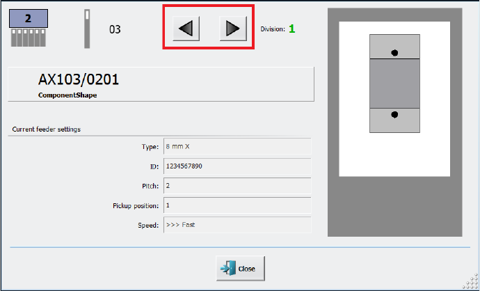
When performing a scan request for a feeder, it is possible to switch between feeder divisions in
the Scan Request dialog.
After clicking the scan request button on the feeder or after ordering a scan request in ASM Setup
Center, the Scan Request dialog opens in the station GUI. In this dialog, you can navigate
between feeder divisions by clicking on the arrow buttons next to the division number.
Figure 4-3: Buttons for navigating between divisions in Scan Request dialog
For easier visibility the number of the currently selected feeder division has been further
highlighted. The division number is now displayed in a bigger font in an extra field and blinks.
Restrictions
– The feature is only supported for the following feeder types that have multiple divisions or
channels:
– Smartfeeder 2x8mm Xi Splice, item no. [00141499-xx]
– Smartfeeder 2x8mm Xi, item no. [00141479-xx]