00198765-02_VD_SSW_713.1_R20-1_EN_DE - 第16页
Station Software 713.1 (R 20-1) / V ersion Description 05/2020 Edition 16 On a non-mast er station, the name of th e master statio n (if available) a nd the connection s tatus to the master station are additionally displ…
Station Software 713.1 (R20-1) / Version Description 05/2020 Edition
15
4.6 Synchronizing Recalibrations of All SIPLACE Stations Along the
Line
Compatible mode: Hidden
The recalibration procedure can now be synchronized for all SIPLACE stations along the line to
minimize the overall downtime of that line. For this, one SIPLACE station in the line assumes the
role of “master station”. When a recalibration is triggered on a station that is connected to the
master station, all other reachable SIPLACE stations along the line are triggered to start the same
recalibration procedure as the master station.
If a non-master SIPLACE station cannot be reached when the synchronized recalibration is
triggered, e.g. because it is offline at that specific moment, its recalibration is done unsynchronized.
If a station is triggered to start a synchronized recalibration while it is producing, the station stops
production and starts the recalibration procedures. If the station is triggered to start a synchronized
recalibration while it is already recalibrating, the triggered recalibration procedure is added to the
recalibration job queue, i.e. the recalibration procedure is done after the current recalibration
procedure is finished. If a recalibration triggered by the master station is already performed during
the currently running recalibration procedure on the station, it will not be added to the recalibration
job queue. If the station is triggered to start a synchronized recalibration while it is being stopped,
e.g. by a user or due to an error, the recalibration procedure is added to the recalibration job queue
and is done after the station has been restarted.
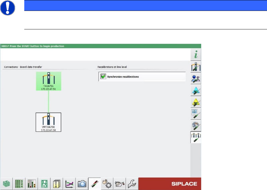
In the Machine neighborhood settings in the station GUI, you can view information on the
synchronized recalibration in the Recalibrations at line level area on the right. Depending on
which role the station has during the synchronized recalibration, different information is displayed.
On the master station, only the Synchronize recalibrations option is visible. If the option is
activated, the recalibration is synchronized along the line. If the option is deactivated, all machines
recalibrate independently.
NOTICE
The Synchronize recalibrations option can only be activated or deactivated on the
master station.
Figure 4-6: Machine neighborhood view with recalibration information on a master station
Station Software 713.1 (R20-1) / Version Description 05/2020 Edition
16
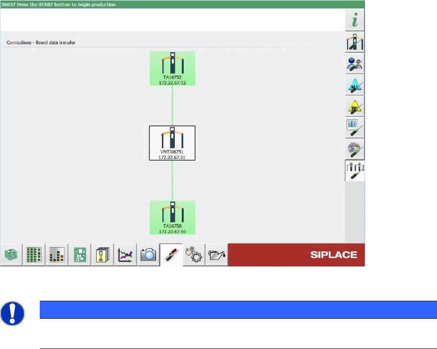
On a non-master station, the name of the master station (if available) and the connection status to
the master station are additionally displayed. If the master station is highlighted in green, the
connection is established successfully. If the master station is highlighted in red, the connection
failed, e.g. because the master station is offline.
Figure 4-7: Machine neighborhood view with recalibration information on a non-master station
NOTICE
Please note that this feature is not displayed with any icon in the production view for
either state (switched on/off).
4.7 Verifying Vacuum Tooling by Barcode Fiducial
Compatible mode: Not supported
Vacuum tooling uses suction to pick up a PCB and hold it precisely and level on a vacuum plate
(tool top plate of vacuum tooling) during the placement process, establishing optimal conditions for
accurate placement. The different vacuum tooling types are often designed for specific PCB types
only. Using a wrong vacuum tooling type can not only lead to inaccurate placements, but also to
damaging or destroying a PCB. To make sure that the correct vacuum tooling types have been
installed in the station, they must be checked against the vacuum tooling types defined in the
vacuum tooling configurations specified in SIPLACE Pro.
Whenever you use vacuum tooling in a station, you need to configure it in the recipe in SIPLACE
Pro and in the station software. To verify that the correct vacuum tooling has been installed in the
station, the configuration on the station is compared with the specifications in the recipe.
To automatically identify the vacuum tooling installed in the station, a barcode fiducial can be used
that is placed on the vacuum tooling surface. The barcode contains information on the vacuum
tooling, e.g. its name and exact vacuum tooling type.
Station Software 713.1 (R20-1) / Version Description 05/2020 Edition
17
In order to locate the barcode on the vacuum tooling, the following parameters must be specified in
SIPLACE Pro:
● The dimension of the vacuum tooling (length and width)
● The X-/Y-offset of the barcode fiducial in relation to the reference point
● The reference to the barcode fiducial
● The barcode verification string
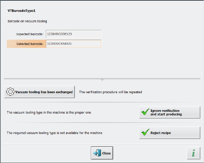
During recipe download, when the conveyor is empty, the lifting table is lifted to upper position,
where the barcode on the tooling surface can be scanned by the PCB camera. The information
contained on the barcode is then compared to the specifications in the recipe. If the barcode
cannot be read, if the vacuum tooling type is unknown, or if the information in the barcode does not
match the data stored in the station software configuration, a detailed error message is displayed:
Figure 4-8: Displayed error message if barcode information does not match recipe