OM-1683-001_w.pdf - 第18页
1 OM-1683 1. Scope In the dual transfer mode (PCB transfer using two transfer lanes), the PCBs with the size (Direction Y) up to 250 mm, can be produced simultaneously . The transfer specications do not comply with the …

OM-1683
Cont-4
Contents
Page
1103-001
15. Pneumatic and Electrical Diagrams ...............................................
39
15.1 Pneumatic and Mounting Diagrams ........................................ 39
Conveyor (Pneumatic Diagram) .................................... 39
Conveyor (Mounting Diagram) ...................................... 40
15.2 Sensor and Load Layout ......................................................... 41
Conveyor Section Layout (Outside : A-Lane) ................ 41
Conveyor Section Layout (Outside : B-Lane) ................ 42
Conveyor Section Layout (Inside : A-Lane) ................... 43
Conveyor Section Layout (Inside : B-Lane) ................... 44
15.3 Parts Location ......................................................................... 45
Conveyor Section Layout .............................................. 45
15.4 Circuit Diagram ....................................................................... 46
Conveyor M Circuit Diagram (1) .................................... 46
Conveyor M Circuit Diagram (2) .................................... 47
Conveyor M Circuit Diagram (3) .................................... 48
Conveyor M Circuit Diagram (4) .................................... 49
Conveyor M Circuit Diagram (5) .................................... 50
Conveyor M Circuit Diagram (6) .................................... 51
Conveyor M Circuit Diagram (7) .................................... 52
Conveyor M Circuit Diagram (8) .................................... 53
Conveyor M Circuit Diagram (9) .................................... 54
Conveyor M Circuit Diagram (10) .................................. 55
U08 I/O P.C.B. STLT CNVR (L) ..................................... 56
U08 I/O P.C.B. STLT CNVR (R) ..................................... 57
15.5 Cable Connection Diagram ..................................................... 58
Dual Transfer Harness Connection Diagram 1 .............. 58
Dual Transfer Harness Connection Diagram 2 .............. 59
16. Specications ................................................................................. 60
1
OM-1683
1. Scope
In the dual transfer mode (PCB transfer using two transfer lanes), the PCBs
with the size (Direction Y) up to 250 mm, can be produced simultaneously.
The transfer specications do not comply with the SMEMA transfer
standards.
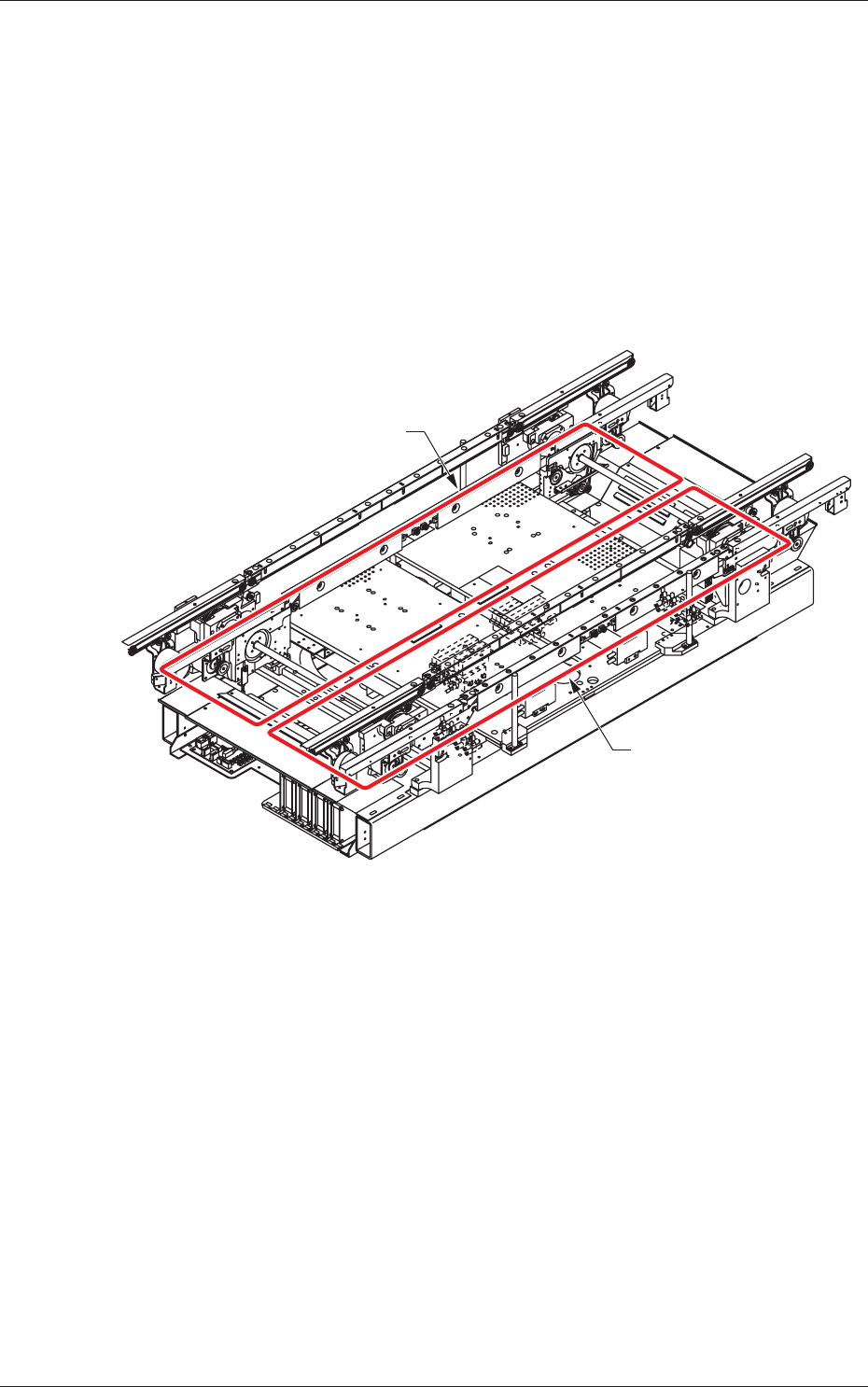
2. Rough View of Machine
Front Side of Machine
Lane A
Lane B
Fig. 1
1103-001
1. Scope
2
OM-1683
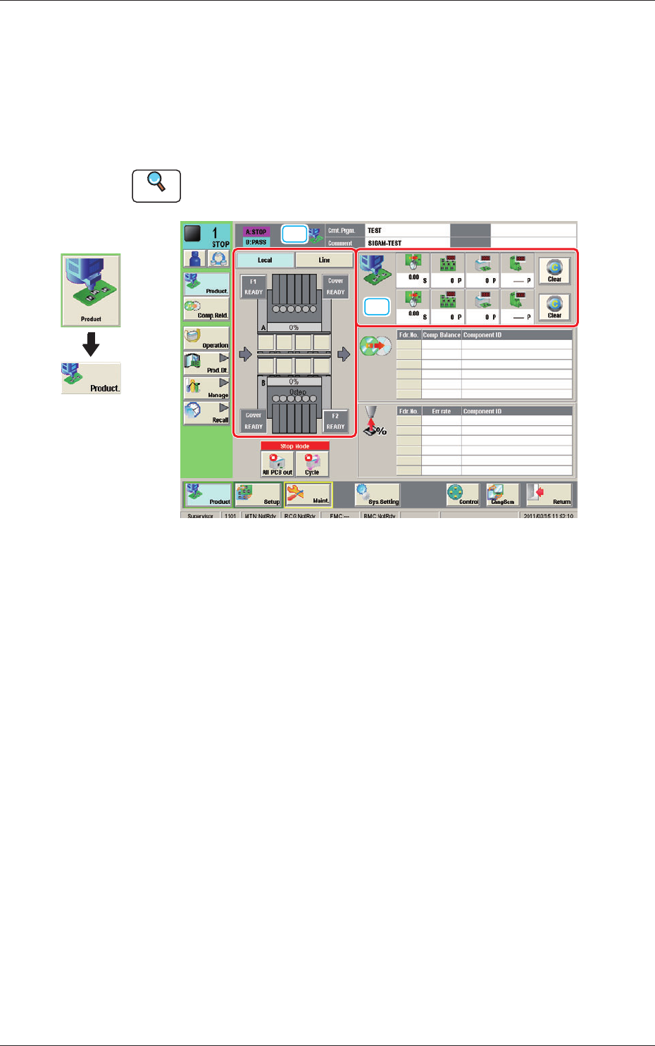
3. Automatic Operation
This window enables you to view the current operation status and production
condition such as the production model names (pattern program names), etc.,
and the information on the prospective number of nished PCBs and presumable
deterioration in the operation rate based on pickup errors, etc.
Reference
Refer to "2.1 "Local" Window" in Chapter 1, Volume 2, in the SIGMA-G5 main
machine instruction manual for the information other than for dual transfer.
[1]
[2]
Fig. 2 Automatic Operation
Graphic
Development
1103-001
3. Automatic Operation